
User's Manual


AT7120 Owner Manual Rev. 1.1 – March 2009 9/76
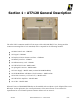
Module 4407
60W UHF band multistage amplifier
The IF modulated signal (previously converted into UHF) is amplified by a 60W UHF amplifier. This
amplifier uses transistors built with LDMOS technology operating in a class AB configuration, which
provides excellent efficiency and linearity. The RF OUT connector of the unit provides the high power
RF output.
RF Output monitoring
Module 4407 detects the direct and reverse RF power present on the RF OUT connector of the unit. The
detected information is then converted to correspondent DC levels before being routed to the master
control unit, where it is processed and displayed at the front panel LCD screen in watts.
Module 4442
AT7120 transmitter has two Modules 4442 connected in parallel, which work as digital TV end
amplifiers in all UHF band. The amplifier is made of the following components:
Input Coupler
The input RF coupler equally divides the UHF signal present in the input connector for the two
amplification cells, maintaining 50Ω impedance.
Cell A – 35W Amplifier
The amplification cell A is obtained by a Push-Pull 35W amplifier, class AB. Transistor T1 is in this
cell. The polarization circuit of cell A is made of a VGS timer circuit with temperature compensation,
differential amplifier and gate impedance reducer.
Cell B – 35W Amplifier
Just as cell A, cell B’s amplification is obtained by a Push-Pull 35W amplifier, class AB. Transistor T2 is in this
cell. The polarization circuit in cell B also is made of a VGS timer circuit with temperature compensation,
differential amplifier and gate impedance reducer.
Output Coupler
It is a hybrid coupler built with a special semi-rigid coaxial cable, better known as “wireline”. This type
of cable has 2 internal conductors interlinked; this set has the characteristics of a hybrid coupler. As the
input coupler, this coupler also has four gates (input/output; isolated, -3dB 0˚, -3 dB 90˚).
Temperature Alarm
Module 4442 has a protection circuit that disarms the module in case the temperature rises above 65˚ C.
This circuit is basically made of thermal sensor S1, DC amplifier and voltage comparator CI-1.