
User's Manual Part 1


AT7400 Owner Manual Rev. 2.0 – October 2006 -10-23 Section 3 - 37/39
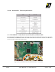
Event Location Alarm set
x Drawer TEMPERATURE.
Module 4455 Above 149°F (+65°C)
x Phase Lock Loops.
Module 4453 Unlock
x 8VSB IF Signals (I/I’) or (Q/Q’). Module 4454 Absence of any
x Master clock
Module 4454 Erratic
x Fan fuse
Transmitter rack Open
The procedure described on this section is validated only if the transmitter operation mode is configured as
AUTOMATIC MODE. (SetUp/Transmit/ReStart: AUTO).
At the time when the transmitter is powered ON, there is a 5s time lapse termed as RAMP TIME. During this
period, the trellis voltage will raise from 0V up to the pre-set nominal level associated with the nominal transmitter
output RF power.
3.11.6.1Off-set Frequency P rogramming
The Linear ATSC/DTV UHF transmitter channel is factory set. On the top of the chosen frequency channel an off-
set frequency can or not be added. If that is the case, the off-set frequency can be positive or negative on values
between as low as 1Hz up to the maximum of 20 kHz.
The digital direct synthesizer circuit, DDS, sub-module 4466, generates the off-set frequency at steps of 1Hz. The
chosen off-set value is however programmed at the PCB CIM 3297, which is than feed-backed to the DDS sub-
module, throughout the pins #3, #4, #5 and #7 at the connector CON-4.
Every time when the transmitter is powered on, the PCB CIM 3297 at the exciter drawer automatically sets the
programming for the up-converter sub-module 4466. The initial program set to the PCB CIM 3297 is made in the
factory by means of the LCD touch screen display, but not accessible to the user during the transmitter field
operation.
3.11.6.2 Re-powering the Power Supply
The SCU PCB located at the exciter drawer, CIM 3297, controls the exciter drawer power supply, sub-module
4456. The main commands are RE-POWERING, and SHUT DOWN, represented by +5V for able, or 0V for
disable. These commands act as protection commands.
The RE-POWERING information (+5V), is available at the pin #5 at the connector CON-11. In case of the
absence of this voltage, the sub-module 4456 interrupts the +32V ON/OFF power supply one, that feeds the 30W
UHF ATSC driver power amplifier, sub-module 4455.
The SHUT DOWN information (+5V), is available at the pin #1 at the connector CON-3. In case of presence of
this voltage, interrupts the power supplies drain with the voltages of +2.5V, +5V, +15V, -15V and +32V ON/OFF.
It is important to note that the +32V FIXED voltage (feeds the DC/DC converter, sub-module 4147, that is
connected to the MCU), and the +15V DIRECT voltage (feeds the PCB CIM 3297 at the exciter drawer) are not
affect by the SHUT DOWN command.