Instructions, Repair and Parts Dyna-Star® 312350E HYDRAULIC RECIPROCATOR AND PUMP - For lubricating fluids only 10:1 Ratio Universal Pump and Reciprocator 600 psi (4.1 MPa, 41 bar) Maximum Hydraulic Input Pressure 7500 psi (51 MPa, 517 bar) Maximum Fluid Outlet Pressure Model 247540: Pump, 60 lb Automatic Lube Pump Module Length Model 247443: Pump, 120 lb Drum Length Model 247450: Pump, 400 lb Drum Length Important Safety Instructions Read all warnings and instructions in this manual.
Warnings Warnings The following warnings are for the setup, use, grounding, maintenance, and repair of this equipment. The exclamation point symbol alerts you to a general warning and the hazard symbol refers to procedure-specific risk. Refer back to these warnings. Additional, product-specific warnings may be found throughout the body of this manual where applicable.
Warnings WARNING MOVING PARTS HAZARD Moving parts can pinch or amputate fingers and other body parts. • Keep clear of moving parts. • Do not operate equipment with protective guards or covers removed. • Pressurized equipment can start without warning. Before checking, moving, or servicing equipment, follow the Pressure Relief Procedure in this manual. Disconnect power or air supply. BURN HAZARD Equipment surfaces and fluid that’s heated can become very hot during operation.
Installation Installation Typical Installation of a Suction Feed System F G H J K M N L P E Q D U C R S T B A ti0477a Key: A B C D E F G H J K L Follower plate Weep tube Fluid outlet line (to gun) Drain valve (required) Ground wire Hydraulic return line, minimum 3/4 inch I.D.
Installation Pump Accessories Hydraulic Lines Follower Plate (A): ensures a good prime. Place follower plate on grease and rotate while pressing firmly to level material. Order part number 247700 for 60# and 90# automatic lube pump modules; 247701 for 120# refinery reservoir; or 247702 for 400# refinery reservoir. Shut-off Valves (H, L): installed on the hydraulic supply and return lines. Order Part No. 108537 and 112578. Drain Line: Monitor the weepage of hydraulic fluid or lubricant.
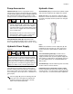
Installation Grounding Grounding the Pump To ground pump (See FIG. 3): 1. Remove ground screw (Z) and insert through eye of ring terminal at end of ground wire. To reduce the risk of static sparking, ground pump. Check your local electrical code for detailed grounding instructions for your area and type of equipment. • Pump: Use ground wire and clamp as shown in FIG. 3. Order Grounding Wire and Clamp Kit, Part No. 222011.
Operation Operation Pressure Relief Procedure Before Starting Pump COMPONENT RUPTURE HAZARD Overpressurizing any component can result in serious injury or property damage as a result of rupture, fire, and/or explosion.The maximum working pressure of each component in the system may not be the same. To reduce the risk of overpressurizing any component in the system: The system pressure must be manually relieved to prevent the system from starting or dispensing accidentally.
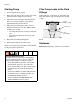
Operation Starting Pump 1. Turn on hydraulic power supply. 2. Open return line shut-off valve (H) first, then slowly open the hydraulic supply shut-off valve (L). If the Pump Leaks at the Fluid Fittings Tighten fittings (1, 5, 60) which are self-sealing and have replaceable o-rings. If leaking persists, change o-rings. 3. Adjust flow control valve (Q) to limit the hydraulic flow to no more than 3 gpm (11 lpm), which is approximately 60 cycles per minute. sealing fitting (1, 5, 60) 4.
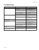
Troubleshooting Troubleshooting Problem Pump does not run. Cause Solution Closed dispense valve. Pump only runs with valve open. Pressure too low. Increase supply pressure using a pressure adjusting valve. Insufficient hydraulic fluid supply. Check hydraulic supply. Adjust to a maximum of 3 gpm (11 lpm) flow. Clogged fluid outlet line, intake valve, Relieve pressure, page 7. Check. dispense valve, suction line. Clear obstructions. Reciprocator damaged. Repair.
Service Service 32 35 Use of a hydraulic power supply with fluid temperatures above 154°F (68°C) can create hot surfaces which can burn if touched. • Do not touch pump, motor, or if hydraulic system fluid is above 154°F (68°C). • Allow sufficient time for pump and motor to cool before attempting any service or repair. 11 3 44 Replacing Throat Seals See FIG. 5. 1 19 Replace throat seals if fluid leaks excessively through the weep tube (B), page 4.
Service Disconnecting Reciprocator and Displacement Pump See FIG. 6 and Displacement Pump Parts, page 18. 1. Flush pump if possible and stop it with displacement rod in lowest position. 2. Relieve pressure, page 7. 60 3 3. Disconnect outlet hose from displacement pump. 36, 37 4. Slowly loosen hydraulic supply (60) and return (5) fittings to relieve any pressure. Then remove hoses. 5 5. Install plugs on tube fittings and in hose ends. 6.
Reciprocator Repair Reciprocator Repair See FIG. 7 and FIG. 9 and Reciprocator Parts, page 18. • Clean and inspect all parts for wear or damage. Replace worn parts as needed. For best results, always replace all the o-rings and seals when you disassemble the pump. Repair Kit 247455 is available. Parts included in the kit are marked with an asterisk, for example (23*), in the text and drawings. Always replace seals (23* and 24*) and seals (16* and 44*) together.
Reciprocator Repair 6. Lay assembly on its side. Place a clean rag around yoke (9) to prevent losing detent balls. Slide yoke (9) sideways off valve sleeve (29) while holding the balls (7) and spring (6) in place. 3, 39, 2 36, 37 30 13* 31 29 38 26 51 6, 7 2 45 9 12 25 12 1 7. Slide cylinder (25) off displacement rod (34). Hold hex end of displacement rod in a vise and use a spanner wrench in pin holes of the piston (22) to screw it off the rod.
Reciprocator Repair 10. Clean all sealant from threads of any part you are reusing. Apply Loctite® 242 or Perma-Loc® 115 thread sealant to first two or three internal threads of valve assembly (31). If you removed capscrew (51) apply thread sealant to first two or three internal threads of valve stop (26). Apply primer to external threads of valve sleeve (29). Let dry for three or four minutes. Assemble. Remove excess sealant. Allow 24 hours to cure before operating reciprocator. 11.
Reciprocator Repair When reinstalling cylinder (25), Step 19, be sure port in valve spool (31) and port in the bottom cylinder cap (32) are in line with each other. Be sure o-rings (13*) are in place in valve spool and cylinder cap. 3, 39, 2 36, 37 13* 31 19. Place cylinder (25) on cylinder cap (32). Install piston (22) and valve assembly (31). 38 25 20. Install o-ring (49*) in deep, lower groove of piston (22). Install seal (23*) over o-ring. Install piston bearing (24*) around upper groove of piston.
Displacement Pump Repair Displacement Pump Repair Disassembly 5. Use wrench to screw shovel (116) off of shovel rod (108). See FIG. 13 for steps 1-10, except where noted. • Be sure you have all necessary parts on hand before you start. If using a repair kit, use all parts in the kit for the best results. • Displacement Pump Repair Kit 241623 is available. Parts included in the kit are marked with a dagger (†) symbol in the parts drawing and list, page 20. 6.
Displacement Pump Repair 107 109 112† 1 7 111† 113 114 108 3 106† 110† 103 7 116 104† 106† 4 102 117 ti10608a Assembled / Cutaway View 1 Using nut (113), torque the pump cylinder 109 to the extension tube (114) at 45 to 55 ft-lb (61 to 75 N.m). 3 Torque the shovel rod (108) to the piston (102) at 25 to 30 ft-lb (34 to 41 N.m). 4 Torque the piston (102) to the extension rod (107) at 25 to 30 ft-lb (34 to 41 N.m). 7 Assemble with lips facing up. ti10609a FIG.
Reciprocator Parts Reciprocator Parts 17 3 36 37 6 39 2 30 60 60a 22 24 49 5 66 6 5 11 3 4 31 5a 45 35 5 16 43 23 61 58 17 9 29 7 44 19 20 4 8 10 21 26 8 6 1 51 20 18 7 52 28 2 1a 27 12 4 15 38 34 5 46 1 6 13 32 71 14 ti10462a 1 Torque to 170-180 in-lbs (19-20 N.m) 2 Torque to 42-45 in-lbs (4-5 N.m). 3 Torque to 54-56 ft-lbs (73-76 N.m). 4 Torque to 54-56 in-lbs (6.0-6.5 N.m). 5 Torque to 40-48 ft-lbs (54-65 N.
Reciprocator Parts Reciprocator Parts Ref. No. 1 Part No. Description Qty. 106470 ELBOW, straight thread, 3/4-16 1 unf-2a x 3/4-16 unf-2a, 37° flare includes item 1a 1a 110987 O-RING 1 2 178179 WASHER, sealing 1 3 160276 CAPSCREW, hex hd, 3/8-24 x 5/8” 1 4* 104093 O-RING 1 5 112568 ADAPTER, pip, 3/4 unf (m) 1/2 npt 1 (f), steel, includes item 5a 5a 110987 O-RING 1 6 108437 SPRING, compression, steel 1 7 100069 BALL, 1/4” dia.
Pump Parts Pump Parts Model 247540 60# Automatic Lube Pump Module Length 201 Ref No. 201 202* 204 205 206▲ Part No. Description RECIPROCATOR, page 18 192533 SEAL, gasket 112154 PIN DISPLACEMENT PUMP 183741 LABEL, identification Qty 1 1 1 1 1 Model 247443 206 120# Drum Length Ref No. 201 202* 204 205 206▲ 202* 204 3 Part No. Description RECIPROCATOR, page 18 192533 SEAL, gasket 112154 PIN DISPLACEMENT PUMP 183741 LABEL, identification Qty 1 1 1 1 1 Model 247450 400# Drum Length 205 2 Ref No.
Technical Data Technical Data Max grease output pressure.............................................. Max hydraulic fluid input pressure.................................... Max hydraulic fluid input volume ....................................... Hydraulic fluid consumption rate..................................... 7500 psi (51 MPa, 517 bar) 600 psi (4.1 MPa, 41 bar) 3 gpm (11.7 lpm), 60 cpm 6.5 ounces (0.195 liter) per cycle or 1 gallon per 19.5 cycles Maximum fluid temperature...........................
Technical Data Dimensions and Mounting Hole Layout 3/4” - 16 JIC 37° flare (m) 3.5 (88.9 mm) minimum diameter clearance hole 3/4 npt Hydraulic Outlet 14.75 in. (375 mm) 1/8 npt throat seal weep port 3.536 in. (90.424 mm) 3.536 in. (90.424 mm) 33.9 in. (861 mm) Model 247540 1/2 npt(f) fluid outlet clearance for, or tap 5/16-18 typical 4 places 41.5 in. (1054 mm) Model 247443 48.5 in.
Notes Notes 312350E 23
Graco Standard Warranty Graco Standard Warranty Graco warrants all equipment referenced in this document which is manufactured by Graco and bearing its name to be free from defects in material and workmanship on the date of sale to the original purchaser for use. With the exception of any special, extended, or limited warranty published by Graco, Graco will, for a period of twelve months from the date of sale, repair or replace any part of the equipment determined by Graco to be defective.