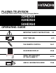
PLASMA TELEVISION AVC (Audio Video Control Center) & Plasma Display Monitor 32HDX60 42HDX60 50HDX60 OPERATING GUIDE IMPORTANT SAFETY INSTRUCTIONS 2-3 Video Audio Ch.
IMPORTANT SAFETY INSTRUCTIONS SAFETY POINTS YOU SHOULD KNOW ABOUT YOUR HITACHI PLASMA TELEVISION Our reputation has been built on the quality, performance, and ease of service of HITACHI Plasma Televisions. Safety is also foremost in our minds in the design of these units. To help you operate these products properly, this section illustrates safety tips which will be of benefit to you.
IMPORTANT SAFETY INSTRUCTIONS Read before operating equipment 15. Televisions are designed to comply with the recommended safety standards for tilt and stability. Do not apply excessive pulling force to the front, or top, of the cabinet which could cause the product to overturn resulting in product damage and/or personal injury. 16. Follow instructions for wall, shelf or ceiling mounting as recommended by the manufacturer. 17.
ACCESSORIES Check to make sure you have the following accessories before disposing of the packing material. REMOTE CONTROL “AA” BATTERIES POWER CORD MONITOR CONNECTION CABLE IR MOUSE CABLE R WE STB PO L FIRST TIME USE CB D R P AR VC CE AM WIZ R PV UR SO TV 3 CD 2 D DV 1 6 5 8 O INF 7 VIDEO 0 ECT ASP T A/V EP SLE 3.
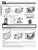
HOW TO SETUP YOUR NEW HITACHI PLASMA TELEVISION SPEAKER INSTALLATION 42” 1. Screw the speaker holder to the speakers as shown below. Speaker Holder Screw x2 Speaker Holder (L) (R) (R) (R) (L) Speaker Holder Speaker Holder 2. 3. 4. 5. 6. Screw x2 Loosen 4 screws (A) (two on the left and two on the right). Completely unscrew 4 screws (B) (two on the left and two on the right). Hook the speaker holders to the loosened screws (A). Screw the speaker holders to the Display Monitor with screws (B).
HOW TO SETUP YOUR NEW HITACHI PLASMA TELEVISION Securing to a table-top 1. Using wood screws (two) fasten the set to the clamping screw holes on the rear of the Plasma Display stand as shown below. 2. Using commercially available wood screws, secure the set firmly in position. Wood screw two places Wood screw two places 42” 32” Securing to a wall 1. Keep the Plasma Display monitor four inches away from the wall except those hung to the wall mount bracket. 2. Secure the monitor to the wall as shown below.
HOW TO SET UP YOUR NEW HITACHI PLASMA TELEVISION BEST VERTICAL VIEWING ANGLE 20 3’ 0’ 5’ 10’ 15’ R S 4" Minimum 50 5’ 4" Minimum 20’ BEST HORIZONTAL 10’ 50 L 15’ 20’ VIEWING ANGLE S IMPORTANT NOTES No. Items Notes 1 Arching sound from A buzzing sound might be heard when the plasma display monitor is turned on in a very quiet plasma display monitor’s room. This is due to the plasma panel drive circuit when it is functioning. This arching sound panel. is normal and it is not a malfunction.
HOOKUP CABLES FIRST TIME USE Most video/audio connections between components can be made with shielded video and audio cables that have phono connectors. For best performance, video cables should use 75-Ohm coaxial shielded wire. Cables can be purchased from most stores that sell audio/video products. Below are illustrations and names of common connectors. Before purchasing any cables, be sure of the output and input connector types required by the various components and the length of each cable.
FRONT PANEL CONTROLS FRONT VIEW 42” DISPLAY MONITOR STANDBY (RED) ON (GREEN) 50” DISPLAY MONITOR FIRST TIME USE 32” DISPLAY MONITOR MAIN POWER STANDBY (RED) ON (GREEN) MAIN POWER STANDBY (RED) ON (GREEN) PULL AUDIO VIDEO CONTROL CENTER AUDIO VIDEO CONTROL CENTER POWER STANDBY (RED) ON (GREEN) VOL- VOL+ CH- CH+ INPUT/EXIT INPUT 5 PHONES S-VIDEO VIDEO L/(MONO) AUDIO R MENU/SELECT MENU/SELECT button This button allows you to enter the MENU
FRONT PANEL CONTROLS FIRST TIME USE POWER button Display Monitor “MAIN POWER” button This power button is for the complete system, and must be turned ON/OFF manually. It is recommended to leave the “MAIN POWER” to ON condition (lights red) for stand-by mode. or STANDBY (RED) ON (GREEN) MAIN POWER MAIN POWER 50” 32”/42” AVC POWER button The AVC power can be turned ON/OFF manually or by remote control.
REAR PANEL JACKS 32”/42” Monitor Bottom View TO CONVERTER ANT B ANT A 2 ANALOG INPUT S-VIDEO S-VIDEO S-VIDEO Y/VIDEO VIDEO VIDEO VIDEO L/(MONO) L/(MONO) PB R AUDIO R R PR MONITOR OUT AUDIO AUDIO INPUT 4 INPUT 3 IR BLASTER L/(MONO) PB R PR AUDIO INPUT 2 15 50” Monitor Bottom View TO MONITOR Y L L Please use HITACHI specified cable.
REAR PANEL JACKS RGB - Analog Input FIRST TIME USE Use this 15-pin D-Sub input for your external devices with RGB output (see page 22). RGB - Audio Input Connect audio for RGB input (if you have mono sound, insert the audio cable into the left audio jack). DVI - HDTV - Digital Input Use this DVI Digital input for your external devices with digital output capability, such as a Set-Top-Box, high band DTV decoders and DVD players with digital content protection (see page 22).
CONNECTING PLASMA DISPLAY MONITOR TO AVC BOX 1. 2. 3. From the owner’s accessory you will find the Monitor Connector cable. Firmly, and securely insert the Monitor Connection Cable to the rear panel of the AVC box “TO MONITOR” connectors. Insert the other ends of the Monitor Connection Cable to the display monitor rear panel “FROM AVC” connectors. FIRST TIME USE Back of Display Monitor 32/42” Back of Display Monitor 50” Core To AC outlet Core To AC outlet Please use HITACHI specified cable.
CONNECTING EXTERNAL VIDEO SOURCES FIRST TIME USE The exact arrangement you use to connect the VCR, camcorder, laserdisc player, DVD player, or HDTV Set Top Box to your Plasma TV is dependent on the model and features of each component. Check the owner’s manual of each component for the location of video and audio inputs and outputs. The following connection diagrams are offered as suggestions. However, you may need to modify them to accommodate your particular assortment of components and features.
CONNECTING EXTERNAL VIDEO SOURCES CONNECTING A STEREO VCR OR STEREO LASERDISC PLAYER Connect the cable from the VIDEO OUT of the VCR or the laserdisc player to the INPUT (VIDEO) jack, as shown on the AVC Center below. 2. Connect the cable from the AUDIO OUT R of the VCR or the laserdisc player to the INPUT (AUDIO/R) jack. 3. Connect the cable from the AUDIO OUT L of the VCR or the laserdisc player to the INPUT (AUDIO/L) jack. 4.
CONNECTING EXTERNAL VIDEO SOURCES FIRST TIME USE CONNECTING S-VIDEO VCR OR LASERDISC PLAYER 1. Connect the cable from the S-VIDEO OUT of the S-VHS VCR or the laserdisc player to the INPUT (S-VIDEO) jack, as shown on the AVC Center below. 2. Connect the cable from the AUDIO OUT R of the VCR or the laserdisc player to the INPUT (AUDIO/R) jack. 3. Connect the cable from the AUDIO OUT L of the VCR or the laserdisc player to the INPUT (AUDIO/L) jack. 4.
CONNECTING EXTERNAL VIDEO SOURCES CONNECTING A STEREO LASERDISC/DVD PLAYER OR HDTV SET TOP BOX TO INPUT 1 OR 2 COMPONENT: Y-PBPR. Connect the cable from the Y OUT of the Laserdisc/DVD player or HDTV set top box to the INPUT (Y) jack, as shown on the AVC Center below. 2. Connect the cable from the CB/PB OUT or B-Y OUT of the Laserdisc/DVD player or HDTV set top box to the INPUT (PB) jack. 3.
CONNECTING EXTERNAL AUDIO/VIDEO DEVICES FIRST TIME USE CONNECTING EXTERNAL AUDIO AMPLIFIER To monitor the audio level of the Plasma TV to an external audio amplifier, connect the system as shown below. The “AUDIO OUT” from the AVC center is a fixed output. The Volume of the amplifier is controlled by the amplifier, not by the Plasma Television. The AUDIO OUT terminal outputs all audio sources (ANT A/B, INPUT 1~5 and RGB).
CONNECTING AV NETWORK The Plasma Television AVC Center has 2 IR BLASTER jacks. Each IR Mouse cable can connect up to 2 external Audio/Video components. Therefore, you can connect the Plasma Television with up to four components. Please see the following example of an AV Network setup between your Hitachi Plasma Television and external Audio/Video equipment (VCR and DVD Player). CONNECTING EXTERNAL AUDIO/VIDEO COMPONENTS TO IR BLASTER FOR AV NETWORK 1.
AV NETWORK SETUP WIZARD 5. Follow the steps below to setup your AV network (See page 21 for AV Network Codes). FIRST TIME USE There are six steps in the setup procedure (DVD setup example below).
AUDIO/VIDEO CODES FOR AV NETWORK (not for remote control) Shogun . . . . . . . . . . . . . . . . . . . . . . . . . . . . . . . . 0240 Singer . . . . . . . . . . . . . . . . . . . . . . . . . . . . . . . . . 0072 Sonic Blue . . . . . . . . . . . . . . . . . . . . . . . . . 0614, 0616 Sony. . . . . . 0035, 0032, 0000, 0033, 0636, 1032, 1232 Sylvania. . . . . . . . . . . . . 0035, 0081, 0000, 0043, 1781 Symphonic . . . . . . . . . . . . . . . . . . . . . . . . . . . . . . 0000 TMK . . . . . . . . . . . . . . .
FIRST TIME USE REAR PANEL CONNECTIONS Outside antenna or cable TV coaxial cable RGB OUTPUT 15 Rear Panel of Display Monitor 14 10 5 13 9 4 12 8 3 11 7 2 2-Way signal splitter 6 1 AUDIO OUT DIGITAL OUTPUT CAPABILITY VCR #1 ANT IN OUTPUT S-VIDEO V DIGITAL OUTPUT L R AUDIO OUT (PROVIDED) TO CONVERTER ANT B ANT A ANALOG INPUT S-VIDEO INPUT S-VIDEO Y/VIDEO OUTPUT VIDEO VIDEO VIDEO L/(MONO) L/(MONO) PB R R R PR AUDIO MONITOR OUT AUDIO AUDIO INPUT 4 INPUT 3 TO MONITOR
TIPS ON REAR PANEL CONNECTIONS • S-VIDEO connections are provided for high performance laserdisc players, VCRs etc. that have this feature. Use these connections in place of the standard video connection if your device has this feature. • Refer to the operating guide of your other electronic equipment for additional information on connecting your hook-up cables.
STB R CBL POWE AMP D E VCR WIZAR TAPE 3 SOURC CD TV 6 2 DVD 9 5 1 INFO 8 4 MODE 0 7 ASPECT NET ANT B EXIT MENU TV/RG A/V SLEEP CH T VID MUTE SVCS VCR E 4 GUIDE/TV LAST CH VID 5 SCHD SELEC VOL FREEZ PLUS+ 3 VID S CH PIP VID 2 VIDEO ACCES PIP VID 1 SWAP PIP MODE PIP REC TSI 5723 CLU- REMOTE In addition to controlling all the functions on your HITACHI Plasma TV, the new remote control is designed to operate different types of VCRs, CATV (Cable TV) conve
HOW TO USE THE REMOTE TO CONTROL YOUR PLASMA TV WIZAR TAPE CBL D STB AMP 3 9 NET INFO EXIT MODE SELEC CH VCR MUTE VID 1 SVCS T PLUS+ VID LAST 2 CH GUIDE/TV PIP MODE VID SCHD 3 CH VID SWAP 4 VID 5 FREEZ PIP ACCES E S VIDEO REC CLU5723 TSI POWER VCR TV CBL STB SOURCE WIZARD CD DVD PVR AMP 1 2 3 4 5 6 7 8 9 0 SLEEP ASPECT O EX NU IT ME SELECT VOL VIDE CH MUT E LAST CH VID 1 VID 2 VID 3 PIP PIP MODE SURF 5 23 VID
HOW TO USE THE REMOTE TO CONTROL YOUR PLASMA TV STB R POWE CBL AMP RD VCR CE WIZA TAPE 3 SOUR TV CD 2 6 DVD 1 5 4 9 INFO 8 MODE 7 T 0 A/V ANT ASPEC NET GB TV/R EXIT MENU P SLEE CH T LAST 4 MUTE SVCS GUIDE/TV CH VID 5 SCHD SELEC VOL VID ZE FREE VCR PLUS+ VID VID 1 3 PIP VID 2 CH SS PIP PIP ACCE VIDEO SWAP PIP MODE REC I 3TS -572 CLU CD, PVR, AMP buttons When pressed, each of these buttons will blink to indicate the remote is in Audio mode or PVR mod
POWE R TV HOW TO USE THE REMOTE TO CONTROL YOUR PLASMA TV VCR DVD SOUR CBL WIZA RD CE CD 1 TAPE STB 2 4 AMP 3 5 7 SLEE P 6 8 ANT TV/RGB 9 0 A/V NET ASPE INFO CT MENU E EXIT MOD VOL SELEC T SVCS CH VCR MUTE VID 1 PLUS+ LAST VID CH 2 PIP GUIDE/TV VID PIP MODE PIP SWAP PIP SCHD 3 CH VID 4 VID 5 FREE ACCE ZE SS VIDEO REC CLU -572 3TS I AV NET button Press this button to access the Audio/Video network (AV Net) menu.
STB R POWE CBL AMP RD VCR CE WIZA TAPE HOW TO USE THE REMOTE TO CONTROL YOUR PLASMA TV 3 SOUR TV CD 2 6 DVD 1 5 4 9 INFO 8 MODE 7 T 0 A/V ANT ASPEC NET GB TV/R EXIT MENU P SLEE CH T LAST 4 MUTE SVCS GUIDE/TV CH VID 5 SCHD SELEC VOL VID ZE FREE VCR PLUS+ VID VID 1 3 PIP VID 2 CH SS PIP PIP ACCE VIDEO SWAP PIP MODE REC I 3TS -572 CLU AV NET LEARNING WIZARD This function of the AV NET makes it more expandable because it allows the user to use equipment th
POWE R TV VCR DVD SOUR CE CD 1 HOW TO USE THE REMOTE TO CONTROL YOUR PLASMA TV CBL WIZA RD TAPE STB 2 4 AMP 3 5 7 SLEE P 6 8 ANT TV/RGB 9 0 A/V NET ASPE MENU E EXIT MOD VOL INFO CT SELEC T SVCS CH VCR MUTE VID 1 PLUS+ LAST VID CH 2 PIP GUIDE/TV VID PIP MODE PIP SWAP PIP SCHD 3 CH VID 4 VID 5 FREE ACCE ZE SS VIDEO REC CLU -572 3TS I ASPECT button Press this button to quickly change the picture format ASPECT ratio.
STB R POWE CBL AMP RD VCR CE WIZA HOW TO USE THE REMOTE TO CONTROL YOUR PLASMA TV TAPE 3 SOUR TV CD 2 6 DVD 1 5 4 9 INFO 8 MODE 7 T 0 A/V P SLEE ASPEC NET GB TV/R EXIT MENU ANT CH T LAST 4 MUTE SVCS GUIDE/TV CH VID 5 SCHD SELEC VOL VID ZE FREE VCR PLUS+ VID VID 1 3 PIP VID 2 CH SS PIP PIP ACCE VIDEO SWAP PIP MODE REC I 3TS -572 CLU (4) RGB (Analog Input) ASPECT DISPLAY MODE.
POWE R TV VCR DVD HOW TO USE THE REMOTE TO CONTROL YOUR PLASMA TV SOUR CE CD 1 CBL WIZA RD TAPE STB 2 4 AMP 3 5 7 SLEE P 6 8 ANT TV/RGB 9 0 A/V NET ASPE MENU E EXIT MOD VOL INFO CT SELEC T SVCS CH VCR MUTE VID 1 PLUS+ LAST VID CH 2 PIP GUIDE/TV VID PIP MODE PIP SWAP PIP SCHD 3 CH VID 4 VID 5 FREE ACCE ZE SS VIDEO REC CLU -572 3TS I LAST CHANNEL (LAST CH) button Use this button to select between the last two channels viewed (good for watching two sporting
STB ER POW CBL VCR CE AMP RD WIZA TAPE 3 SOUR TV CD 2 6 DVD 1 5 4 9 INFO 8 MODE 7 T 0 A/V P SLEE ASPEC NET GB TV/R EXIT MENU ANT CH CT LAST GUIDE/T 4 MUTE SVCS V CH VID 5 SCHD SELE VOL VID ZE FREE VCR PLUS+ VID VID 1 3 PIP VID 2 CH SS PIP P PIP ACCE O VIDE SWA E PIP MOD PICTURE-IN-PICTURE (PIP) REC 3TS I -572 CLU Your HITACHI Plasma TV incorporates Dual Tuner technology designed for improved viewing enjoyment.
POWE R TV VCR DVD SOUR CE CD 1 CBL WIZA RD TAPE STB 2 4 AMP 3 5 7 SLEE P 6 8 ANT TV/RGB 9 0 A/V NET ASPE MENU E EXIT MOD VOL INFO CT SELEC T SVCS CH VCR MUTE VID 1 PLUS+ LAST VID CH 2 PIP GUIDE/TV VID PIP MODE PIP SWAP PIP SCHD 3 CH VID 4 VID 5 FREE ACCE ZE SS VIDEO PICTURE-IN-PICTURE (PIP) REC CLU -572 3TS I POP MODE PIP This feature displays a sub-picture outside of the main picture.
STB R POWE CBL AMP RD VCR CE WIZA TAPE 3 SOUR TV CD 2 6 DVD 1 5 4 9 INFO 8 MODE 7 T 0 A/V ANT ASPEC NET GB TV/R EXIT MENU P SLEE CH T CH VID 5 SCHD SELEC GUIDE/TV LAST VOL 4 MUTE SVCS VID ZE FREE VCR PLUS+ 3 VID VID 1 PIP VID 2 CH SS PIP PIP ACCE VIDEO SWAP PIP MODE PICTURE-IN-PICTURE (PIP) REC I 3TS -572 CLU FREEZE button (With PIP OFF) Press the FREEZE button to freeze the picture, depending on the PIP mode selected (SPLIT, STROBE, MAIN and SUB).
POWE R TV VCR DVD SOUR CE CD 1 CBL WIZA RD TAPE STB 2 4 AMP 3 5 7 SLEE P 6 8 ANT TV/RGB 9 0 A/V NET ASPE MENU E EXIT MOD VOL INFO CT SELEC T SVCS CH VCR MUTE VID 1 PLUS+ LAST VID CH 2 PIP GUIDE/TV VID PIP MODE PIP SWAP PIP SCHD 3 CH VID 4 VID 5 FREE ACCE ZE SS VIDEO USING THE REMOTE TO CONTROL VCR FUNCTIONS REC CLU -572 3TS I Operating the precoded function for your VCR. This remote is designed to operate different types of VCRs.
STB R POWE CBL AMP RD VCR CE WIZA TAPE 3 SOUR TV CD 2 6 DVD 1 5 4 9 INFO 8 MODE 7 T 0 A/V ASPEC NET GB TV/R ANT EXIT MENU P SLEE CH T LAST 4 MUTE SVCS GUIDE/TV CH VID 5 SCHD SELEC VOL VID ZE FREE VCR PLUS+ VID VID 1 3 PIP VID 2 CH SS PIP PIP ACCE VIDEO SWAP PIP MODE REC I 3TS -572 CLU USING THE REMOTE TO CONTROL CABLE BOX FUNCTIONS Operating the precoded function for your cable box.
POWE R TV VCR DVD USING THE REMOTE TO CONTROL SET-TOP-BOX/SATELLITE RECEIVER FUNCTIONS SOUR CE CD 1 CBL WIZA RD TAPE STB 2 4 AMP 3 5 7 SLEE P 6 8 ANT TV/RGB 9 0 A/V NET ASPE MENU E EXIT MOD VOL INFO CT SELEC T SVCS CH VCR MUTE VID 1 PLUS+ LAST VID CH 2 PIP GUIDE/TV VID PIP MODE PIP SWAP PIP SCHD 3 CH VID 4 VID 5 FREE ACCE ZE SS VIDEO REC CLU -572 3TS I Operating the precoded function for your set-top-box/satellite receiver.
STB R POWE CBL AMP RD VCR CE WIZA TAPE 3 SOUR TV CD 2 6 DVD 1 5 4 9 INFO 8 MODE 7 T 0 A/V ASPEC NET GB TV/R ANT EXIT MENU P SLEE CH T LAST 4 MUTE SVCS GUIDE/TV CH VID 5 SCHD SELEC VOL VID ZE FREE VCR PLUS+ VID VID 1 3 PIP VID 2 CH SS PIP PIP ACCE VIDEO SWAP PIP MODE USING THE REMOTE TO CONTROL DVD FUNCTIONS REC I 3TS -572 CLU Operating the precoded function for your DVD player.
POWE R TV VCR DVD USING YOUR REMOTE TO CONTROL ADDITIONAL AUDIO EQUIPMENT AND PVR SOUR CE CD 1 CBL WIZA RD TAPE STB 2 4 AMP 3 5 7 SLEE P 6 8 ANT TV/RGB 9 0 A/V NET ASPE MENU E EXIT MOD VOL INFO CT SELEC T SVCS CH VCR MUTE VID 1 PLUS+ LAST VID CH 2 PIP GUIDE/TV VID PIP MODE PIP SWAP PIP SCHD 3 CH VID 4 VID 5 FREE ACCE ZE SS VIDEO REC CLU -572 3TS I Operating the precoded function for your Audio component.
STB R POWE CBL AMP RD VCR CE WIZA TAPE 3 SOUR TV CD 2 6 DVD 1 5 4 9 INFO 8 MODE 7 T 0 A/V ANT ASPEC NET GB TV/R EXIT MENU P SLEE CH T LAST 4 MUTE SVCS GUIDE/TV CH VID 5 SCHD SELEC VOL VID ZE FREE VCR PLUS+ VID VID 1 3 PIP VID 2 CH SS PIP PIP ACCE VIDEO SWAP PIP THE SIMPLE REMOTE CONTROL MODE REC I 3TS -572 CLU HITACHI has provided a second remote control for your convenience. The Simple Remote Control has the basic features that are most often used.
AUDIO/VIDEO CODES FOR REMOTE CONTROL ONLY R VCR SOUR CE CD 1 CBL WIZA RD TAPE STB 2 AMP 3 5 P 6 8 TV/RGB 9 0 A/V NET ASPE MENU E EXIT VOL INFO CT MOD SELEC T SVCS VCR PLUS+ LAST VID CH 2 PIP CH MUTE VID 1 GUIDE/TV VID PIP MODE PIP SWAP PIP SCHD 3 CH VID 4 VID 5 FREE ACCE ZE SS VIDEO REC CLU -572 3TS I Quarter . . . . . . . . . . . . . . . . . . . . . . . . 18 Quartz . . . . . . . . . . . . . . . . . . . . . . . . . 18 Quasar . . . . . . . . . . . . . . . . . . .
OSD (On-Screen Display) 1. Press MENU on the remote control to display the different features on your HITACHI Plasma TV. A/V Net 2. Use the THUMB STICK to navigate to a different menu item. 3. Press EXIT on the remote control to quickly exit from a menu. NU 4. Press AV NET on the remote control to access the AV Network menu to control external components. ME EX IT SELECT This part of the screen shows which selections are available. Video Audio Aspect Chan.
OSD (On-Screen Display) Picture Mode Contrast Brightness Color Tint Sharpness Color Temperature Video Black Enhancement Contrast Mode Reset Video Settings Color Management Color Decoding Auto Color Select between the two picture modes; Day and Night. Adjust contrast. Adjust brightness. Adjust color. Adjust tint. Adjust sharpness. Set this to High for less intense color with more blue, set to Medium for natural color, set to Standard for standard colors or Black and White for more reddish color.
VIDEO Select VIDEO to adjust picture settings and improve picture quality. You can customize each of the Video Inputs to your preference to increase viewing performance and pleasure depending upon the video program being viewed. If RESET is selected, only the selected mode will reset to initial conditions. Video Picture Mode Use this function to choose from automatic picture settings to optimize your TV’s performance. Video Audio Aspect Chan.
VIDEO Video Video Contrast Aspect Chan. Manager THUMB STICK Locks SELECT Power Swivel Move Day Night 100% Brightness 50% Color 50% Tint Setup NU ME ANT A/B Picture Mode Audio SEL Sel Sharpness 50% Color Temperature High Black Enhancement High Contrast Mode Dynamic Reset Video Settings Move SEL Select Use the THUMB STICK or to highlight the function to be adjusted. Press down on THUMB STICK to select the function settings.
VIDEO This function allows you to Reset the Video Menu Settings of the present input and return it to the Day or Night conditions depending on the selected VIDEO mode.
VIDEO Use this function to adjust the percentage of Red, Green and Color according to the user’s preference. Use TINT to adjust flesh tones so they appear natural. Color Decoding Video Video ANT A/B Color Decoding Color Management Color Decoding Auto Color Off Noise Reduction Low Auto Movie Mode Off Move SEL RGB THUMB STICK Select R G Red 50% Green 50% Color 50% B Tint Reset Move SEL Return Use THUMBSTICK to highlight function. Press down to select from 4 menu items.
AUDIO Select AUDIO to adjust the TV to your preference and to improve the sound quality. Audio Audio Video Audio Aspect THUMB STICK Locks Setup NU ME SELECT Power Swivel Move SEL 45% Bass 50% Balance Chan. Manager THUMB STICK Treble Sel L SRS TruBass High Matrix Surround On Audio Source Stereo Internal Speakers On Auto Noise Cancel On Perfect Volume On Move Change Value SEL R Return Press THUMB STICK , , to select menu item.
ASPECT Aspect Mode Use this function to select the Picture Format Aspect Ratio. Auto Aspect Automatically adjust the Aspect Ratio depending on the input signal to fill the screen. Press THUMB STICK , , to select menu item. Press down on THUMBSTICK to select. A “ ” in the box indicates that the feature is ON. NOTE: See page 29 for Aspect Mode availability. Vertical Position This function allows you to select when aspect style is either 4:3 EXPANDED/ZOOM1/ZOOM2 or 16:9 ZOOM.
CHANNEL MANAGER Chan. Manager Select ANTENNA if you are using an indoor or outdoor antenna. Select Cable if you have cable TV. Chan. Manager Chan. Manager Ant. A Ant. A Ant. B Move SEL Select THUMB STICK Channel Source Antenna SELECT Auto Channel Scan Cable(1) Cable(2) Start Channel List Move SEL Return THUMB STICK Chan. Manager Ant.
CHANNEL MANAGER This feature will automatically store active TV channels in Auto Channel Scan. This will allow you to skip unused channels when using CHANNEL UP ( ) or DOWN ( ). Auto Channel Scan Chan. Manager Chan. Manager Ant. A Ant. A Channel Source Antenna Cable(1) Auto Channel Scan Cable(2) THUMB STICK SEL Cable(1) Auto Channel Scan Start Channel List Move Channel Source Antenna Cable(2) Start Channel List Select Move SEL Select THUMB STICK SELECT Chan. Manager Ant.
CHANNEL MANAGER Channel List This function allows you to review which channels are labeled (CH ID), which have been added to Channel Memory (SCAN), and which are protected by LOCK. Chan. Manager Chan. Manager Channel List Ant.
CHANNEL MANAGER This section contains advanced features which will make TV viewing easier and more enjoyable. Use this feature to give up to 20 channels a name when ANTENNA signal source is selected and up to 60 channels a name when CATV signal source is selected. Channel ID Chan. Manager Chan. Manager Ant. A Ant.
LOCKS This function will block out the picture and sound of the selected channel or video input. It can also be used to keep the TV from being viewed for a scheduled time period that you set. Locks The code to enter the Locks feature is a four digit secret code number. The factory preset code is 0000. Use the number buttons to select secret code. Video Audio Aspect Chan.
LOCKS Movie Ratings Use MOVIE RATINGS to prevent viewing of any movie that you feel may be inappropriate due to its content. Locks Locks Movie Ratings Change Access Code Engage Lock THUMB STICK TV Time Lock THUMB STICK Movie Ratings Status Not Rated: G: PG: TV Ratings NU SELECT ME PG-13: Canadian Ratings (Eng) R: Canadian Ratings (Frn) Move SEL Select NC-17: X: Move SEL Return Use THUMB STICK or to select the MOVIE RATING category that you want to block.
LOCKS TV Ratings Use TV RATINGS to prevent the viewing of any TV program that you feel may be inappropriate due to its content. Locks Locks TV Ratings Change Access Code Sub Category Engage Lock THUMB STICK TV Time Lock THUMB STICK Movie Ratings D L S V FV TV-Y: TV-Y7: TV Ratings NU Status SELECT ME Canadian Ratings (Eng) TV-G: Canadian Ratings (Frn) TV-PG: Move SEL Select TV-14: TV-MA: Move SEL Return Use THUMB STICK or to highlight the category that you want to block.
LOCKS Canadian Ratings (Eng) Use Canadian Ratings (Eng) to block various types of movies and television programs used in Canada that you feel may be inappropriate due to its content.
LOCKS Canadian Ratings (Frn) Use CANADIAN RATINGS (FRN) to block Canadian French programs according to various program ratings that you feel may be inappropriate due to its content.
SETUP Setup Select SETUP when setting up your TV for the first time. Use the THUMB STICK or on the remote to highlight the function desired. Video Setup Menu Preference Audio Screen Saver Aspect THUMB STICK THUMB STICK Chan. Manager Locks NU ME SELECT Setup Set The Inputs Set The Color System Set Black Side Panel Power Swivel Move Set The Clock SEL Set Event Timer Sel Set Closed Captions Move SEL Select Use THUMB STICK or to select the sub-menu of your choice.
SETUP Menu Background This function allows you to choose from two menu backgrounds. Setup Menu Preference Set The Language English French THUMB STICK Spanish Set The Menu Background Shaded Solid Move SEL Select Use THUMB STICK , to highlight SET THE MENU BACKGROUND (shaded or solid), and press down on THUMB STICK to select the setting. Press EXIT to quit the menu. Select SOLID and background is visible (no picture can be seen behind menu screen), select SHADED and a light background is visible.
SETUP The time must be set before you can Set Event Timer or TV Time Out. Set The Clock Setup Setup Menu Preference Set The Clock Screen Saver Set The Clock Set The Inputs THUMB STICK Time : Tue --:-- PM Move Set The Color System SEL Return SELECT Set Black Side Panel Set Event Timer Set Closed Captions Move SEL Select THUMB STICK Setup Set The Clock Time : Tue --:-- PM Move SEL Return Use THUMB STICK or to set the time, and day of the week.
SETUP Set The Inputs Use this feature to give a name to any of the five video inputs.
SETUP Video 2 Auto Link Use this function to automatically turn the TV on and tune to Video 2 when it detects a video signal to input 2.
SETUP Set Event Timer This function will automatically turn the Plasma TV on and off, one time only, every day, or once a week. If the clock is not set, you can not use this function and the screen below will appear. The message on the screen will disappear after 3 seconds, then the screen automatically goes to the clock setup mode (see page 61). Please Set Clock First.
SETUP Closed Captions are the dialogue, narration, and/or sound effects of a television program or home video which are displayed on the Plasma Television screen. Your local TV program guide denotes these programs .
POWER SWIVEL Power Swivel This feature controls the motorized stand for the 32” and 42” models. It allows the customer to turn the plasma display left or right using the remote control. Video Audio Aspect Chan. Manager THUMB STICK Locks SELECT Setup Power Swivel Move SEL Sel Power Swivel Move SEL Return Use THUMB STICK to rotate the TV to the right. Use THUMB STICK to rotate the TV to the left. Release the THUMBSTICK to stop rotation. 1.
RGB ON SCREEN DISPLAY IMPORTANT: TURN OFF THE AVC BOX, THE DISPLAY MONITOR AND THE EXTERNAL COMPONENT BEFORE CONNECTING OR DISCONNECTING ANY CABLES.
USING THE RGB INPUT RGB ON SCREEN DISPLAY 2. The new setting (horizontal position, vertical position, clock, and phase) of the signal will be stored. The monitor can store up to 13 settings in addition to the 15 pre-set signal timing. Any additional new settings (more than 15) will over-write the first user’s setting, second setting and so on. 3. Operation in RGB mode in relation to TV functions are shown below. No.
RGB ON SCREEN DISPLAY 5. Input signal level. SYNC TTL level H/V separate signal RGB INPUT 0.7Vpp/1.0Vpp NOTE: Interlaced signal is not available. 6. RGB input signal will not appear at all when receiving a signal which is not supported by this product. If the setting is wrong, the Display Monitor will display: NO SYNC. SIGNAL INVALID SCAN FREQ. Without sync Either horizontal or vertical frequency is inappropriate or out of range. INVALID SCAN FREQ. will disappear after 60 seconds.
RGB ON SCREEN DISPLAY USING THE RGB INPUT 1. Press TV/RGB button on the remote control to switch between TV and RGB modes. 2. Press MENU on the remote control to display the different features in RGB MODE. RGB TV/ 3. Press the THUMB STICK , , , buttons to highlight a different feature. NU ME EX 4. Press EXIT on the remote control to quickly exit from a menu. SELECT Video Aspect Setup Power Swivel Move SEL Sel This part of the screen shows which Remote Control buttons to use.
RGB ON SCREEN DISPLAY Video Aspect Setup Power Swivel Enhancer Reset Change the contrast between black and white levels in the picture. Adjust overall picture brightness. Select between HIGH (9,300K), MEDIUM (7,500K), STANDARD (6,500K), or Black/White (5,400K). Enhance picture details (Off, Low, Medium or High). Recall the factory preset data of the RGB Video Settings. Real Normal Full Aspect as it is presented in its true resolution. Aspect in 4:3 standard. Aspect in 16:9 standard.
RGB ON SCREEN DISPLAY The following adjustments are independent of the TV mode: •Press MENU in RGB mode for on screen display. •Press THUMB STICK or to highlight the item to be adjusted. •Press SELECT to select the highlighted item. USING THE RGB INPUT VIDEO ADJUSTMENTS CONTRAST This feature allows you to adjust the contrast in RGB mode. Use THUMB STICK or to adjust contrast. Press MENU button to return to RGB MODE MENU and EXIT to quit.
RGB ON SCREEN DISPLAY Enhances the picture detail. ENHANCER 100% Contrast Brightness 50% Color Temperature High Enhancer Off Reset Reset Move SEL Select Set CONTRAST, BRIGHTNESS, COLOR TEMPERATURE, and ENHANCER to factory preset condition. RESET Video 100% Contrast Brightness 50% Color Temperature High Enhancer Off Reset Press down on THUMB STICK to RESET to factory preset settings.
RGB ON SCREEN DISPLAY USING THE RGB INPUT AUTO ADJUST HORIZONTAL POSITION, VERTICAL POSITION, HORIZONTAL CLOCK and CLOCK PHASE for current RGB format are adjusted automatically. Setup Auto Adjust Adjust Horizontal Position 0 Vertical Position 0 Horizontal Clock 0 Clock Phase 0 Reset Reset Input Level 0.7V Black Side Panel Off Move Press SELECT to select AUTO ADJUST. Select SEL NOTE: • • • • • Press SELECT to AUTO ADJUST the RGB mode.
RGB ON SCREEN DISPLAY HORIZONTAL CLOCK Adjusts the pixel clock frequency to reduce the vertical stripe. Auto Adjust Adjust Horizontal Position 0 Vertical Position 0 Horizontal Clock 0 Clock Phase 0 Reset Reset Input Level 0.7V Black Side Panel Off Move NOTE: Use THUMB STICK , to adjust the horizontal clock. Press the MENU button to return to previous menu. Press EXIT to quit.
RGB ON SCREEN DISPLAY USING THE RGB INPUT RGB ASPECT DISPLAY MODE. RGB (Analog) INPUT SIGNAL Others SVGA/XGA(4) VGA 480p X REAL REAL REAL(1) ASPECT NORMAL NORMAL NORMAL NORMAL(1) MODE FULL FULL FULL(1) AVAILABILITY FULL 720p 1080i X X X X FULL(2,3) FULL(2,3) For numbers in ( ), please see corresponding note below. NOTES: 1. 2. 3. 4. Lack of raster can be seen in RGB when a 480p signal is input. AUTO ADJUST function (see page 74) is not available in 720p, 1080i, and 480p input signal.
CARE OF YOUR HITACHI PLASMA DISPLAY AND YOUR REMOTE CONTROL DO Dust the screen and frame with a cleaning cloth from the accessories pack. Clean the screen and frame with a soft cloth moistened in warm water and dry with a soft cloth. A mild soap may be used if the screen is extremely dirty. Place your Plasma Television away from extreme heat, humidity, and extremely dusty places.
USEFUL INFO • IGNITION NOISE: Black spots or horizontal streaks may appear, picture may flutter or drift. Usually caused by interference from automobile ignition systems, neon lamps, electrical drills, and other electrical appliances. • GHOSTS: Ghosts are caused by the television signal following two paths. One is the direct path and the other is reflected from tall buildings, hills or some other objects. Changing the direction or position of the antenna may improve reception.
No Picture, no sound Sound OK, picture poor Picture OK, sound poor Picture blurred Lines or streaks in picture Poor reception on some channels Picture rolls vertically TV rd cor is p rec lug t is s g ed wit an che in oth d''O er N" cha Ch nn eck e l (s an ten tat ion na Ch tro eck con ub ne an le) ctio ten n n Ch s( af ba or eck c bro ko ou ken fT tsid V) Ch lea ea eck d-i nte nw nn for a i r loc e al i Ad nte jus tC rfe ren on
PLUG and PLAY This Plasma Television complies with VESA DDC2B specifications, Plug & Play is a system with computer, peripherals (including monitors) and operating system. It works when the monitor is connected to a DDC ready computer that is running an operating system software that is capable for the plug & play. When a Plug and Play PC is powered on, it sends a command to the Monitor requesting identification. The Monitor sends back a string of data including its characteristics.
USEFUL INFO AGENCY REGULATORY INFORMATION Federal Communications Commission Notice This equipment has been tested and found to comply with the limits for a Class B digital device, pursuant to Part 15 of the FCC Rules. These limits are designed to provide reasonable protection against harmful interference in a residential installation.
USEFUL INFO Audio: Features: • • • • • • • • • • • • • • • New Easy-to-Use On-Screen Menu Control (3 Language) New AV Network System Control Control up to 4 components with one remote 2 IR Mouse cables included Control Codes Stored in AV Control Center Two Tuner Split Screen except RGB modes.
USEFUL INFO To locate an authorized HITACHI service facility in the continental U.S.A. and Canada, DIAL TOLL FREE 7 days a week, 24 hours a day (1-800-448-2244) Hitachi has made every effort to assure you hours of trouble free operation from your unit. However, should you require service, a network of Hitachi Authorized Service Facilities has been established in all 50 states and Puerto Rico. Each facility will provide you with convenient and expedient assistance.
USEFUL INFO Hitachi Canada, LTD. Digital Media Division Should you have any questions regarding warranty, service, operation, or technical assistance, please contact: In Canada: 1-800-HITACHI (1-800-448-2244) Monday - Friday EST 9:00am - 7:00pm Saturday EST 9:00am - 5:00pm Look for your French Manual on the outside of the box. If the manual is missing, call 1-800-HITACHI (1-800-448-2244) for a copy.
INDEX A Accessories, . . . . . . . . . . . . . . . . . . . . . . . . . . . . . . .4 Antennas (Connecting), . . . . . . . . . . . . . . . . . . . . . . .8 Aspect Ratio, . . . . . . . . . . . . . . . . . . . . . . . . . . . . . .29 Audio (Sound Enhancement) TruBass . . . . . . . . . . . . . . . . . . . . . . . . . . . . . . . .48 Audio Settings . . . . . . . . . . . . . . . . . . . . . . . . . . . . .48 Audio Source . . . . . . . . . . . . . . . . . . . . . . . . . . . . . .48 Auto Adjust (RGB Input) . . . .
NOTES 86
NOTES 87
QR57972