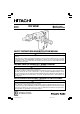
Model Modèle Modelo DH 50SB Rotary Hammer Marteau rotatif Martillo perforador SAFETY INSTRUCTIONS AND INSTRUCTION MANUAL WARNING IMPROPER OR UNSAFE use of this power tool can result in death or serious bodily injury! This manual contains important information about product safety. Please read and understand this manual BEFORE operating the power tool. Please keep this manual available for other users and owners before they use the power tool. This manual should be stored in safe place.
CONTENTS English Page IMPORTANT SAFETY INFORMATION ................ 3 MEANINGS OF SIGNAL WORDS ........................ 3 SAFETY ...................................................................... 4 GENERAL SAFETY RULES ................................... 4 SPECIFIC SAFETY RULES AND SYMBOLS ......... 6 DOUBLE INSULATION FOR SAFER OPERATION ................................................... 8 Page ASSEMBLY AND OPERATION ............................... 10 APPLICATIONS .................................
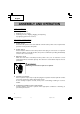
English IMPORTANT SAFETY INFORMATION Read and understand all of the safety precautions, warnings and operating instructions in the Instruction Manual before operating or maintaining this power tool. Most accidents that result from power tool operation and maintenance are caused by the failure to observe basic safety rules or precautions. An accident can often be avoided by recognizing a potentially hazardous situation before it occurs, and by observing appropriate safety procedures.
English SAFETY GENERAL SAFETY RULES WARNING: Read and understand all instructions. Failure to follow all instructions listed below, may result in electric shock, fire and/or serious personal injury. SAVE THESE INSTRUCTIONS 1. 2. 3. 4 Work Area (1) Keep your work area clean and well lit. Cluttered benches and dark areas invite accidents. (2) Do not operate power tools in explosive atmospheres, such as in the presence of flammable liquids, gases, or dust.
English 4. 5. (4) Remove adjusting keys or wrenches before turning the tool on. A wrench or a key that is left attached to a rotating part of the tool may result in personal injury. (5) Do not overreach. Keep proper footing and balance at all times. Proper footing and balance enables better control of the tool in unexpected situations. (6) Use safety equipment. Always wear eye protection. Dust mask, non-skid safety shoes, hard hat, or hearing protection must be used for appropriate conditions.
English SPECIFIC SAFETY RULES AND SYMBOLS 1. 2. 3. 4. 5. 6. 7. 8. 9. 10. 11. 12. 13. 14. Hold tools by insulated gripping surfaces when performing an operation where the cutting tool may contact hidden wiring or its own cord. Contact with a “live” wire will make exposed metal parts of the tool “live” and shock the operator. ALWAYS wear ear protectors when using the tool for extended periods. Prolonged exposure to high intensity noise can cause hearing loss.
English 15. Operate power tools at the rated voltage. Operate the power tool at voltages specified on its nameplate. If using the power tool at a higher voltage than the rated voltage, it will result in abnormally fast motor revolution and may damage the unit and the motor may burn out. 16. NEVER use a tool which is defective or operating abnormally.
English DOUBLE INSULATION FOR SAFER OPERATION To ensure safer operation of this power tool, HITACHI has adopted a double insulation design. “Double insulation” means that two physically separated insulation systems have been used to insulate the electrically conductive materials connected to the power supply from the outer frame handled by the operator. Therefore, either the symbol “ ” or the words “Double insulation” appear on the power tool or on the nameplate.
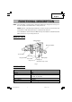
English FUNCTIONAL DESCRIPTION NOTE: The information contained in this Instruction Manual is designed to assist you in the safe operation and maintenance of the power tool. NEVER operate, or attempt any maintenance on the tool unless you have first read and understood all safety instructions contained in this manual. Some illustrations in this Instruction Manual may show details or attachments that differ from those on your own power tool.
English ASSEMBLY AND OPERATION APPLICATIONS 䡬 䡬 䡬 Drilling anchor holes Drilling holes in concrete Crushing concrete, chipping, digging, and squaring (by applying optional accessories) PRIOR TO OPERATION 1. Power source Ensure that the power source to be utilized conforms to the power source requirements specified on the product nameplate. 2. Power switch Ensure that the switch is in the OFF position.
English 6. How to install dust cover (Fig. 2) Always install the dust cover on the drill bit or the taper shank adaptor. Insert the dust cover until it lies flush in the groove. NOTE: For a thick drill bit, insert the dust cover from drill rear. Dust cover Insert up to the groove Fig. 2 7. How to install tool CAUTION: For tools such as a bull point and a cold chisel, use only Hitachi genuine parts. (1) Clean, then smear the tool shank with the grease provided.
English 2. How to chip or crushing (1) Use the D type handle. (2) By applying the bull point tip to the chipping or crushing position, operate the rotary hammer by utilizing its own weight. Forcible pressing or thrusting is unnecessary. DRILLING AND DRIVING-IN OPERATIONS FOR ANCHORS Use the optional accessories for anchors, such as anchor adapter and taper shank adapter. 1. When a rotation-striking anchor adapter is used. (1) Install the self-drilling anchor in the anchor adapter (Fig. 6).
English 2 . How to use the drill bit (taper shank) and the taper shank adaptor. (1) Install drill bit with taper shank in the taper shank adaptor. (Fig. 10) (2) Turn the power on and drill a base hole. (3) After cleaning out dust with a syringe, attach the plug to the anchor tip and drive in the anchor with a manual hammer. (4) To remove the drill bit with taper shank, insert a cotter into the slot of the taper shank adaptor, place supports under the Rotary Hammer and tap the cotter with a manual hammer.
English (2) Mount the core bit shank on the main body in the same manner as in mounting the drill bit and the bull point. (Fig. 13) (3) Insert the center pin into the guide plate until it reaches the extremity. (4) Fit in the guide plate by aligning its concaved portion with the core bit tip. When the position of the concave is shifted by turning the guide plate right or left, the guide plate never slips off even when the rotary hammer is used in a downward direction. (Fig. 14) 2.
English MAINTENANCE AND INSPECTION WARNING: Be sure to switch power OFF and disconnect the plug from the receptacle during maintenance and inspection. 1. Inspecting the drill bits Since use of a dull tool will cause motor malfunctioning and degraded efficiency, replace the drill bit with a new one or resharpening without delay when abrasion is noted. 2. Inspecting the screws Regularly inspect all screws and ensure that they are properly tightened.
English 䡬 Replacing carbon brushes: (For parts name, refer to Fig. 1) Loosen the set screw then remove the cap cover. Remove the brush cap and carbon brush. After replacing the carbon brush, do not forget to tighten the brush cap securely and to install the cap cover. 5. How to replace grease 䡬 䡬 This machine is full air-tight construction to protect against dust and to prevent lubricant leakage. Therefore, the machine can be used without lubrication for long periods.
English CAUTION: Repair, modification and inspection of Hitachi Power Tools must be carried out by a Hitachi Authorized Service Center. This Parts List will be helpful if presented with the tool to the Hitachi Authorized Service Center when requesting repair or other maintenance. In the operation and maintenance of power tools, the safety regulations and standards prescribed in each country must be observed.
English ACCESSORIES WARNING: ALWAYS use Only authorized HITACHI replacement parts and accessories. NEVER use replacement parts or accessories which are not intended for use with this tool. Contact HITACHI if you are not sure whether it is safe to use a particular replacement part or accessory with your tool. The use of any other attachment or accessory can be dangerous and could cause injury or mechanical damage. NOTE: Accessories are subject to change without any obligation on the part of the HITACHI.
English 2. Anchor hole drilling (Rotation + Hammering) (3) Cotter (1) Drill bit (Taper shank) (2) Taper shank adaptor (Spline shank) A-taper B-taper 3. Taper shank adaptor formed A-taper or B-taper is provided as optional accessory, but drill bit for it is not provided Large-dia. hole boring (Rotation + Hammering) (Guide plate) (1) Center pin (2) Core bit External dia. 2" (50 mm) 4-1/8" (105 mm) 5" (125 mm) 4.
English 6. Asphalt cutting (Hammering) (1) Cutter Overall length Width 1-1/2" (38 mm) 2" (50 mm) 12" (300 mm) 7. Digging (1) Scoop 8. Syringe (for chip removal) NOTE: Specifications are subject to change without any obligation on the part of the HITACHI.
Français INFORMATIONS IMPORTANTES DE SÉCURITÉ Lire et comprendre toutes les précautions de sécurité, les avertissements et les instructions de fonctionnement dans ce mode d’emploi avant d’utiliser ou d’entretenir cet outil motorisé. La plupart des accidents causés lors de l’utilisation ou de l’entretien de l’outil motorisé proviennent d’un non respect des règles ou précautions de base de sécurité.
Français SECURITE REGLES GENERALE DE SECURITE AVERTISSEMENT: Lire et coxmprendre toutes les instructions. Un non respect de toutes les instructions ci-dessous peut entraîner une électrocution, un incendie et/ou de sérieuses blessures personnelles. CONSERVER CES INSTRUCTIONS 1. 2. 3. Zone de travail (1) Garder la zone de travail propre et bien éclairée. Les établis mal rangés et les zones sombres invitent aux accidents.
Français 4. 5. (2) S’habiller correctement. Ne pas porter des vêtements larges ou des bijoux. Attacher les cheveux longs. Tenir ses cheveux, vêtements et ses gants éloignés des parties mobiles. Les vêtements larges, les bijoux et les cheveux longs peuvent se prendre dans les parties mobiles. (3) Eviter tout démarrage accidentel. S’assurer que le l’interrupteur d’alimentation est sur la position d’arrêt avant de brancher la machine.
Français (2) Lors de la réparation d’un outil, utiliser uniquement des pièces de rechange identiques. Suivre les instructions de la section d’entretien de ce mode d’emploi. L’utilisation de pièces non autorisées ou un non respect des instructions d’entretien peut créer un risque d’électrocution ou de blessures. REGLES DE SECURITE SPECIFIQUES ET SYMBOLES 1. 2.
Français 11. Maintenir toutes les vis, tous les boulons et les couvercles fermement en place. Maintenir toutes les vis, tous les boulons et les couvercles fermement montés. Vérifier leurs conditions périodiquement. 12. Ne pas utiliser les outils motorisés si le revêtement de plastique ou la poignée est fendu. Des fentes dans le revêtement ou la poignée peuvent entraîner une électrocution. De tels outils ne doivent pas être utilisés avant d’être réparé. 13.
Français Avant l’utilisation, vérifier s’il y a des objets dissimulés, par exemple des câbles électriques, dans le mur, le plancher ou le plafond. 22. Définitions pour les symboles utilisés sur cet outil V ............ volts Hz .......... hertz A ............ ampères no .......... vitesse sans charge W ........... watt .......... Construction de classe II ---/min ... tours par minute ..........
Français DESCRIPTION FONCTIONNELLE REMARQUE: Les informations contenues dans ce mode d’emploi sont conçues pour assister l’utilisateur dans une utilisation sans danger et un entretien de l’outil motorisé. NE JAMAIS utiliser ni entreprendre une révision de l’outil sans avoir d’abord lu et compris toutes les instructions de sécurité contenues dans ce manuel. Certaines illustrations dans ce mode d’emploi peuvent montrer des détails ou des accessoires différents de ceux de l’outil motorisé utilisé.
Français ASSEMBLAGE ET FONCTIONNEMENT APPLICATIONS 䡬 䡬 䡬 Perçage de trous d’ancrage Perçage de trous dans béton Broyage du béton, burinage, creusage et équarrissage (par application des accessoires optionnels) AVANT L’UTILISATION 1. Source d’alimentation S’assurer que la source d’alimentation qui doit être utilisée est conforme à la source d’alimentation requise spécifiée sur la plaque signalétique du produit. 2. Interrupteur d’alimentation S’assurer que l’interrupteur est sur la position OFF (arrêt).
Français 6. Comment installer le cache-poussière (Fig. 2) Toujours installer le cache-poussière sur le raccord de la queue conique. Insérer le cachepoussière bien à fleur de la rainure. REMARQUE: Pour une mèche épaisse, insérer le cache-poussière par l'arrière de la mèche. Insérer jusqu’à Cache- la rainure poussière Fig. 2 7. Comment installer l’outil PRECAUTION: Pour les outils tels que pointe de broyage et ciseau à froid, n’utiliser que des pièces HITACHI d’origine.
Français PRECAUTION: Bien que cette machine soit équipée d’un cran de sécurité, si la mèche est prise dans le béton ou autre matériel l’arrêt de son fonctionnement pourrait faire tourner le corps de la machine. Tenir fermement la poignée principale et la poignée de type barre pendant le fonctionnement. Poignée de type D 2. Comment broyer du béton et buriner (1) Utiliser la poignée de type D.
Français ATTENTION La partie conique vole lorsqu’elle est coupée. Il faut donc faire attention à la direction de découpe. Chasse-clavette Gouge 2. Comment utiliser la mèche (queue conique) et le raccord de queue conique. (1) Installer la mèche à queue conique dans le raccord de queue conique. (Fig. 10) (2) Mettre l’appareil sous tension et percer un trou de base. (3) Après avoir retirer la poussière avec une seringue, fixer le mandrin à la pointe du sabot et l’enfoncer dans le sabot avec un marteau.
Français COMMENT UTILISER LA COURONNE Lorsqu’une couronne est utilisée, il est possible de percer des orifices de gros calibre et des trous borgnes. Dans ce cas, utiliser les accessoires en option pour les couronnes tels qu’un goujon central et une queue de couronne) pour une utilisation plus rationnelle. 1. Montage PRECAUTION: Avant de monter une couronne, débrancher toujours l’outil de la prise d’alimentation. Couronne (1) Monter la couronne sur la queue de couronne. (Fig.
Français 3. Comment démonter la couronne (Fig. 16) (1) En tenant droit le marteau rotatif (sur lequel la couronne est insérée), faire tourner le marteau rotatif de manière à répéter deux ou trois fois l’impact afin de desserrer la vis. Le marteau rotatif peut alors être démonté. (2) Ôter la queue de couronne du marteau rotatif, maintenir la couronne d’une main et frapper fortement deux ou trois fois la tête de la partie hexagonale de la queue de couronne avec un marteau manuel.
Français ENTRETIEN ET INSPECTION AVERTISSEMENT: S’assurer de mettre l’interrupteur d’alimentation sur la position OFF et de déconnecter la fiche de la prise secteur avant l’entretien et l’inspectio. 1. Contrôle du foret de perçage Etant donné que l’utilisation d’une mèche usée entraînera un mauvais fonctionnement du moteur et une diminution de l’efficacité, remplacez la mèche usée par une neuve ou aiguisez-la immédiatement et dès que vous notez une certaine usure. 2.
Français 䡬 Remplacement du balais en carbone (Pour les noms des parts, voyez la Fig. 1) Desserrer la vis boulonnée et retirer le couvercle du bouchon. Retirer le bouchon de charbon et le balai de charbon. Après avoir remplacé le balai de charbon, ne pas oublier de serrer le bouchon de charbon à fond et de remonter le couvercle du bouchon. 5.
Français PRECAUCIÓN: Les réparations, modifications et inspections des outils électriques Hitachi doivent être confiées à un service après-vente Hitachi agréé. Il sera utile de présenter cette liste de pièces au service après-vente Hitachi agréé lorsqu’on apporte un outil nécessitant des réparations ou tout autre entretien. Lors de l’utilisation et de l’entretien d’un outil électrique, respecter les règlements et les normes de sécurité en vigueur dans le pays en question.
Français ACCESSOIRES AVERTISSEMENT: TOUJOURS utiliser UNIQUEMENT des pièces de rechange et des accessoires HITACHI. Ne jamais utiliser de pièce de rechange ou d’accessoires qui ne sont pas prévus pour être utilisé avec cet outil. En cas de doute, contacter HITACHI pour savoir si une pièce de rechange ou un accessoire particulier peuvent être utilisés en toute sécurité avec votre outil.
Français 2. Perçage de trous d’ancrage (rotation + percussion) (3) Clavette (1) Mèche (2) Raccord de queue conique (queue conique) (queue cannelée) Cône-A Cône-B 3.
Français 6. Coupage d’asphalte (Percussion) (1) Fraise Longueur totale 12" (300 mm) Largeur 1-1/2" (38 mm) 2" (50 mm) 7. Puisage (1) Bourroir 8. Seringue (pour enlever déchets) REMARQUE: Les spécifications sont sujettes à modification sans aucune obligation de la part de HITACHI.
Español INFORMACIÓN IMPORTANTE SOBRE SEGURIDAD Antes de utilizar o de realizar cualquier trabajo de mantenimiento de esta herramienta eléctrica, lea y comprenda todas las precauciones de seguridad, advertencias e instrucciones de funcionamiento de este Manual de instrucciones. La mayoría de los accidentes producidos en la operación y el mantenimiento de una herramienta eléctrica se deben a la falta de observación de las normas o precauciones de seguridad.
Español SEGURIDAD NORMAS GENERALES DE SEGURIDAD ADVERTENCIA: Lea y entienda todas las instrucciones. Si no sigue las instrucciones indicadas a continuación, pueden producirse descargas eléctricas, incendios, y/o lesiones serias. GUARDE ESTAS INSTRUCCIONES 1. 2. 3. Área de trabajo (1) Mantenga el área de trabajo limpia y bien iluminada. Los bancos de trabajo desordenados y las áreas obscuras pueden conducir a accidentes.
Español 4. 5. (2) Vístase adecuadamente. No utilice ropa floja ni joyas. Si tiene pelo largo, recójaselo. Mantenga su pelo, ropa, y guantes alejados de las partes móviles. La ropa floja, las joyas, o el pelo largo pueden engancharse en las partes móviles. (3) Evite la puesta en marcha accidental. Cerciórese de que la alimentación de la herramienta eléctrica esté desconectada antes de enchufarla en una toma de la red.
Español (2) Para el servicio de mantenimiento o reparación de una herramienta, utilice solamente piezas de repuesto idénticas. Siga las instrucciones de la sección de mantenimiento de este manual. La utilización de piezas no autorizadas, o el no seguir las indicaciones del Manual de instrucciones puede crear el riesgo de descargas eléctricas u otras lesiones. NORMAS Y SÍMBOLOS ESPECÍFICOS DE SEGURIDAD 1. 2.
Español 11. Mantenga todos los tornillos, pernos, y cubiertas firmemente fijados en su lugar. Mantenga todos los tornillos, pernos, y cubiertas firmemente montados. Compruebe periódicamente su condición. 12. No utilice herramientas eléctricas si la carcasa o la empuñadura de plástico está rajada. Las rajas en la carcasa o en la empuñadura de plástico pueden conducir a descargas eléctricas. Tales herramientas no deberán utilizarse mientras no se hayan reparado. 13.
Español 22. Definiciones para los símbolos utilizados en esta herramienta V ............ voltios Hz .......... hertzios A ............ amperios no .......... velocidad sin carga W ........... vatios .......... Construcción de clase II ---/min ... revoluciones por minuto .......... Corriente alterna AISLAMIENTO DOBLE PARA OFRECER UNA OPERACIÓN MÁS SEGURA Para garantizar una operación más segura de esta herramienta eléctrica, HITACHI ha adoptado un diseño de aislamiento doble.
Español DESCRIPCIÓN FUNCIONAL NOTA: La información contenida en este Manual de instrucciones ha sido diseñada para ayudarle a utilizar con seguridad y mantener esta herramienta eléctrica. NUNCA haga funcionar ni efectúe el mantenimiento de la herramienta antes de leer y comprender todas las instrucciones de seguridad contenidas en este manual. Algunas ilustraciones de este Manual de Instrucciones pueden mostrar detalles o accesorios diferentes a los de la propia herramienta eléctrica.
Español MONTAJE Y OPERACIÓN APLICACIONES 䡬 䡬 䡬 Perforación de orificios de anclaje Perforación de orificios en hormigón Trituración de hormigón, cincelado, excavación y escuadreo (utilizando accesorios opcionales) ANTES DE LA OPERACIÓN 1. Fuente de alimentación Cerciórese de que la fuente de alimentación que vaya a utilizar cumpla los requisitos indicados en la placa de características del producto. 2. Interruptor de alimentación Cerciórese de que el interruptor de alimentación esté en la posición OFF.
Español 6. Instalación de la cubierta para polvo (Fig. 2) Siempre hay que instalar la cubierta para polvo (protectora) en el adaptador de espiga de barrena perforadora. Insertar la cubierta para polvo hasta que se encaja en la ranura. NOTA: Para una barrena gruesa insertar la cubierta para polvo por su parte posterior. Inserte hasta la ranura Cubierta para polvo Fig. 2 7.
Español PRECAUCIÓN: Aunque este aparato se equipa con un embrague de seguridad, si se atasca la barrena de taladrar en el hormigón u otro material semejante, puede pasar que, al atascarse la barrena, el cuerpo del martillo gire en dirección opuesta. Asegúrese de que la empuñadura principal y la empuñadura tipo barra están sujetas firmemente durante la operación. Empuñadura tipo D 1. Cómo cincelar o perforar (1) Utilice la empuñadura tipo D.
Español (4) Tras introducir el ancla, utilice la llave de empuje para separar el ancla. (Fig. 8) (5) Al utilizar un martillo de mano o pinzas, retire la parte barrenada del ancla. (Fig. 9) Llave perforadora Gubia PRECAUCIÓN: Como la parte barrenada retirada saldrá volando, preste atención a la dirección de rotura. Fig. 8 2. Utilización de la broca de barrena (barrena ahusada) y del adaptador de barrena ahusada (1) Instale la broca con la barrena ahusada en el adaptador de barrena ahusada. (Fig.
Español MODO DE USAR LA BARRENA TUBULAR Cuando se utiliza una barrena tubular, pueden perforarse orificios de calibre grande y orificios ciegos. En este caso, utilice accesorios opcionales para barrenas tubulares (como un pasador central y una espiga de barrena) para una operación más racional. 1. Montaje PRECAUCIÓN: Antes de instalar la barrena tubular, desconecte el enchufe de la corriente. Barrena tubular (1) Montar la barrena tubular en su espiga. (Fig.
Español 3. Desmontaje (Fig. 16) (1) Sujetando el martillo perforador (con la broca introducida) en posición hacia arriba, utilice el martillo perforador para repetir la operación de impacto dos o tres veces; la parte roscada se aflojará y el martillo perforador podrá quitarse.
Español MANTENIMIENTO E INSPECCIÓN ADVERTENCIA: Antes de realizar el mantenimiento o la inspección de la amoladora, cerciórese de desconectar la alimentación y de desenchufar el cable de alimentación del tomacorriente. 1. Inspeccionar la broca de taladro Debido a que el uso de brocs desafiladas pueden causar mal funcionamiento del motor y desmejorar la eficacia del taladro, hay que reemplazar las brocas en malas condiciones por nuevas o afilarlas de inmediato al advertir abrasión. 2.
Español 䡬 Cambio de escobillas de carbón (Para los nombres de las partes, vea la Fig. 1) Afloje el tornillo de ajuste y retire la cubierta de la tapa. Retire la tapa del portaescobilla y la escobilla de carbón. Después de reemplazar la escobilla de carbón, no olvide de apretar firmemente la tapa del portaescobilla y de instalar la cubierta de la tapa. 5. Cambio de grasa Esta máquina es de construcción completamente cerrada, para evitar que entre polvo y haya fugas de lubricante.
Español PRECAUCIÓN: La reparación, modificación e inspección de las herramientas eléctricas Hitachi deben ser realizadas por un Centro de Servicio Autorizado de Hitachi. Esta lista de repuestos será de utilidad si es presentada junto con la heramienta al Centro de Servicio Autorizado de Hitachi para solicitar la reparación o cualquier otro tipo de mantenimiento. En el manejo y el mantenimiento de las herramientas eléctricas, se deberán observar las normas y reglamentos vigentes en cada país.
Español ACCESORIOS ADVERTENCIA: UTILICE únicamente repuestos y accesorios autorizados por HITACHI. No utilice nunca repuestos o accesorios no previstos para usar con esta herramienta. Si tiene dudas en cuanto a la seguridad de usar determinado repuesto o accesorio junto con su herramienta, póngase en contacto con HITACHI. La utilización de otros accesorios puede resultar peligrosa y causar lesiones o daños mecánicos. NOTA: Los accesorios están sujetos a cambio sin ninguna obligación por parte de HITACHI.
Español 2. Perforación de orificio de anclaje (Rotación + martilleo) (3) Cortadora (1) Barrena (espiga cónica) (2) Adaptador de espiga cónica (espiga ranurada) Cono A Cono B 3.
Español 6. Corte de asfalto (Martilleo) (1) Cortadora Largo total 12" (300 mm) 7. Anchura 1-1/2" (38 mm) 2" (50 mm) Trabajos con cuchara (1) Cuchara 8. Jeringa (extracción de resíduos) NOTA: Las especificaciones están sujetas a cambio sin ninguna obligación por parte de HITACHI.
03Spa_DH50SB_US 59 25/5/07, 17:00
03Spa_DH50SB_US 60 25/5/07, 17:00
A 1 2 3 4 5 6 7 8 10 11 12A 13A 14 15 16 17 18 21A 22 23 24 25 26 27 28 29 30 31 32 33 34 35 36 37 40 41 42 43A 44 45A 46 47 48 49 50 51 52 53 54 55 56 57 58 59 60 61 62 63 64 65 66 67 68 69 B 993231 971750 993252 985773 955593 985772 993247 993237 949432 985779 327733 327736 939542 980756 985771 986960 983162 991716 980749 980744 985763 932815 948227 985765 6204DD 980750 980727 984509 949656 986963 986962 986961 944951 961400 985471C 937623 985435 994085 983362 999071 961781 981959 958715 938477 ———— 9495
03Spa_DH50SB_US 62 25/5/07, 17:00
03Spa_DH50SB_US 63 25/5/07, 17:00
WARNING: Some dust created by power sanding, sawing, grinding, drilling, and other construction activities contains chemicals known to the State of California to cause cancer, birth defects or other reproductive harm. Some examples of these chemicals are: ● Lead from lead-based paints, ● Crystalline silica from bricks and cement and other masonry products, and ● Arsenic and chromium from chemically-treated lumber. Your risk from these exposures varies, depending on how often you do this type of work.