
Owners manual


8
English
ASSEMBLY PROCEDURES
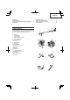
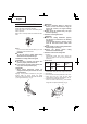
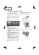
Installation of handle (Fig. 1)
Attach the handle to the drive shaft tube.
Adjust the location to the most comfortable position
before operation.
Make sure to securely attach the handle with the 4
bolts.
1
Fig. 1
NOTE
If your unit has handle location label (1) on drive
shaft tube, follow the illustration.
WARNING
Do not use metal or plastic blade cutting
attachments with loop handle type.
Installation of cuttingt attachment guard
WARNING
● Do not start or operate unit unless each
guard is properly assembled to unit.
● If an incorrect or faulty guard is fi tted, this
may cause serious personal injury.
CAUTION
Some cutting attachment guards are
equipped with sharp line limiters. Be careful
with handling it.
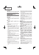
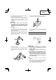
Aligning to the position indicated by the guard
location label (2), fi rmly secure the cutting
attachment guard to the drive shaft tube with the bolt
(3) and guard bracket (4). (Fig. 2)
4
2
3
Fig. 2
WARNING
● lf unit is operated without a sharp line
limiters, the line will become too long, the
engine will overheat, and engine damage
may occur.
● Check sharp line limiters surely cut nylon
line when operating.
Installation of cutting attachment
WARNING
● Install the cutting attachment properly
and securely as instructed in the handling
instructions.
If not attached properly or securely, it may
come off and cause serious and/or fatal
injury.
● Do not install or remove cutting attachments
while the engine is running.
● Always use genuine Hitachi cutting
attachments and metal fi ttings.
Installation of semi-auto cutting head
1. Function
Automatically feeds more nylon cutting line
when it is tapped at low rpm (not greater than
6,000 min
–1
).
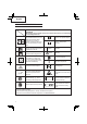
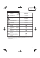
Specifi cations
Code No.
Type of
attaching
screw
Direction of
rotation
Size of
attaching
screw
6600570
Female
screw
Counterclockwise
M10×P1.25-
LH
Applicable nylon cord
Cord diameter: 3/22˝ (Φ2.4 mm) Length: 16.3 ft (5 m)
2. Precautions
○ The case must be securely attached to the cover.
○ Check the cover (5), case (6) and other
components for cracks or other damage. (Fig. 3)
○ Check the case and button for wear.
If there is a hole in the bottom (7) of the button,
change the new parts immediately. (Fig. 3)
7
6
5
Fig. 3
000Book_CG23ECP_US.indb 8000Book_CG23ECP_US.indb 8 2015/11/20 11:39:132015/11/20 11:39:13