ENGLISH USER'S MANUAL CMP4201 CMP4202 Thank you very much for purchasing the HITACHI Plasma Display Monitor. Before using your monitor, please carefully read the "SAFETY GUIDELINES" and this "USER'S MANUAL" so you will know how to operate the monitor properly. Keep this manual in a safe place. You will find it useful in the future. Notes on lnstallation Work: This product is marketed assuming that it is installed by qualifed personnel with enough skill and competence.
FEATURES Large-screen, high-definition plasma display panel The 42-inch color plasma display panel, with a resolution of 1024 (H) x 1024(V) pixels, creates a high-definition, large-screen (aspect ratio : 16:9) and low-profile flat display. Free from electromagnetic interferences from geomagnetic sources and ambient power lines, the panel produces high-quality display images free from color misconvergence and display distortion.
This monitor is designed to be safe to use. However, fire or serious injury may occur unless you use this monitor in the proper way. Please follow the instructions shown below in order to avoid injury.
SAFETY GUIDELINES(continued) WARNING Fire or electric shock may cause death or serious injury unless you follow the instruction. • The enclosed power cord must be used! Failure to do so may cause electric shock hazard or fire hazard. In USA/Canada, use a UL LISTED/CSA LABELLED or CERTIFIED power cord set meeting the following specifications : Rating: min. 125V, 10A , Length: max. 3.
CAUTION You may have serious injury or your property may be damaged unless you follow the instruction below. • Do not coil or wind the power cord. This may cause excessive heat resulting in a fire. • Caution for 200 - 240V operation only This equipment relies on the protective devices in the building installation for short - circuit and over - current protection.
SAFETY GUIDELINES(continued) PRECAUTIONS(continued) • How to clean the monitor. Before cleaning the monitor, turn off the monitor and disconnect the power plug from the mains. When cleaning the monitor, do not spray directly the screen or cabinet with cleaner. Use a clean, dust free, dry and soft cloth. If it is not enough, then use a cloth with non-alcoholic or non-ammonia detergent. Do not rub the surface of the screen with ball-point-pen or screw-driver etc.
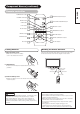
This product is complete with the display monitor, plus the accessories shown below. • If any of these accessories is missing, please contact your dealer. VOL MUTE VOL AUTO PinP SIZE RECALL RGB 1 RGB 2 VIDEO 1 VIDEO 2 MENU RETURN ENTER ID User manual (this book) ID SET Remote-control transmitter Size AA batteries x 2 Power cable • Read the user manual (this book) and keep them in a safe place for handy reference. •Retain the packing materials for use in future shipping or relocation.
Component Names Front Main Unit Cabinet Panel (front frame) The stand shown is optional. Control panel • Adjustment buttons are located on the bottom. • The back cover is provided with indications to distinguish the adjustment buttons. Remote-control receiver Indicator lamp • The main power switch is located at the back, on the lower surface.
Remote controller POWER OFF button POWER ON/OFF button POWER ON button MUTE button VOLUME UP/DOWN button SIZE button VOL PinP button MUTE VOL AUTO PinP SIZE RECALL RGB 1 RGB 2 VIDEO 1 VIDEO 2 RECALL button AUTO button MENU button MENU RGB/VIDEO buttons RETURN RETURN button ENTER ENTER button ID ID SET ID SET button ID button Loading Batteries 1. Open the battery cover. • Slide back and remove the battery cover in the direction of the arrow.
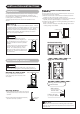
INSTALLATION INSTRUCTIONS Using the optional vertical-mount unit (CMPAK15) Installation No stand is provided with this product. When installing the monitor, use the optional Desk-top Stand (CMPAD05), Wall Mount Unit (horizontal-mount CMPAK05, vertical/horizontal-mount CMPAK15), or Ceiling Mount Unit (CMPAT05). The Desk-top Stand has been used for the illustrations in this manual. WARNING Use one of the special mount units to install this product.
INSTALLATION INSTRUCTIONS (continued) to ) carefully to ensure maximum safety before ENGLISH Read SAFETY GUIDELINES ( proceeding to these steps: • Choose an appropriate site and install the product on a level table where the stand is secure. • Install the monitor to have ready access to a power socket available. • Make sure that the power switch of this device is turned off.
INSTALLATION INSTRUCTIONS (continued) Connecting to a Video Imaging Device (When the optional video unit is installed.) (1) Make sure that the power switch of the imaging device is turned off. (2) Use a commercially available cable and connector to connect the signal input terminal on the rear panel of this device and the signal output terminal of the imaging device.
Power Cord Connection Connect the power cord, after completing all other connections. (1) Connect the power cord to this device. (2) Connect the power cord plug to the power outlet. CAUTIONS • Use only the power cord provided. • Do not use a power supply voltage other than that indicated (AC100-240V, 50/60Hz) as this may cause fire or electrie shock. • To maintain the correct performance level, use a 3-core power cord with ground wire attached.
OPERATING INSTRUCTIONS Turning Power On and Off Indicating lamp Main power switch To turn the monitor power ON, press the main power switch on the monitor main unit to ON, and then press the SUB POWER button or the ON/OFF or ON button on the remote control. To turn the monitor power OFF, press the SUB POWER button or the ON/OFF or OFF button on the remote control, and then press the main power switch on the monitor main unit to OFF.
OPERATING INSTRUCTIONS (continued) The volume can be adjusted by pressing the VOL+ and VOL- buttons of the remote control (or the ▲ and ▼ volume buttons of the monitor unit) while the on-screen display system is not being displayed. Volume setting value VOLUME buttons VOLUME 15 INPUT SELECT button Adjustment status guide display • When a button is pressed, the volume adjustment status guide will be displayed.
OPERATING INSTRUCTIONS (continued) Displaying Two Screens If the PinP button on the remote control is pressed when the optional video unit is installed, two screens will display. Activating the P-in-P mode from the RGB input screen Pressing the PinP button one time will display two screens. The speaker icon can be shifted left and right by pressing the and SELECT buttons; the audio of the video will be output from the R1 V1 side on which the speaker icon is located.
Using the Menu Screen (On-screen display system) VOL MUTE VOL AUTO PinP SIZE RECALL RGB 1 RGB 2 VIDEO 1 VIDEO 2 When the MENU button is pressed, the adjustment menu screen will be displayed; from there, video adjustment and setting is possible by using the SELECT button, ADJUST button and ENTER button. AUTO button MENU button MENU RETURN SELECT/ADJUST buttons ENTER • Refer to settings.
OPERATING INSTRUCTIONS (continued) PICTURE MENU (This function can only be used when the optional video unit has been inserted.
PICTURE MENU (continued) Selected characters Setup hint SHARPNESS Picture is soft Picture is sharp In general, position is in the center and shift to the minus (-) side when a softer effect is desired. VIDEO PICTURE NORMAL SOFT Use SOFT when DVD, video and other images become harsh or picture noises on the screen is evident. Use NORMAL as standard. CONTRAST MODE DYNAMIC:Emphasizes the differences between video shadings to improve the feeling of contrast.
OPERATING INSTRUCTIONS (continued) (This function can only be used when the optional video unit has been inserted.
OPERATING INSTRUCTIONS (continued) ENGLISH DISPLAY MENU (continued) Display area selection diagram (RGB input) Resolution Full display Display FULL Circular display NORMAL REAL ZOOM1 ZOOM2 ZOOM3 640 X 480 (VGA) 800 X 600 (SVGA) 1024 X 768 (XGA) 1280 X 1024 (SXGA) 1600 X 1200 (UXGA) * VGA and W-VGA only Processes such as compression (thinning) and expansion are performed for the above signal display.
OPERATING INSTRUCTIONS (continued) DISPLAY MENU (continued) TIPS Using a wide-screen monitor • This monitor has a screen mode selection feature. If an incompatible screen mode is selected to play certain software, such as a TV program, the image would appear different from the original. Take this into consideration when making screen mode choices.
OTHER MENU MAIN MENU PICTURE SOUND DISPLAY FUNCTION OTHER MENU SEL. ENT ENT. RTN END Selected characters AUTO DISPLAY OTHER MENU AUTO DISPLAY : ON OFF TIMER : OFF LANGUAGE : ENGLISH ID NO. : 1 ORBITER : OFF MOVING TIMER : 10MINITE INVERSE : OFF WHITE : OFF SEL. ADJ. RTN BACK Setup hint Set to ON. Information is displayed when switching inputs and changing signals. Set to OFF. Information is not displayed when switching inputs and changing signals.
OTHER FEATURES Automatic Store Approximately 1 sec. after adjustment is completed, the adjustments will be recorded as shown in the table below. Menu Display Registration condition PICTURE OPERATE MODE VIDEO LEVEL 3D COMB SOUND VOLUME BALANCE TREBLE BASS MUTE LEVEL DISPLAY SIDE AREA FUNCTION RGB1 SIGNAL RGB2 SIGNAL COMPONENT1 COMPONENT2 COMPONENT (VIDEO2) COLOR SYSTEM OTHER AUTO DISPLAY LANGUAGE ID NO. ORBITER MOVING TIMER INVERSE WHITE PICTURE DISPLAY Menu PICTURE DISPLAY Can register 1 group.
Power Save Mode When the RGB input is selected • When this unit is connected to a VESA DPMS computer, the Power Save (Off) mode can be set to be activated automatically when the computer is not being used to reduce power consumption by this unit.
IMAGE RETENTION OF PLASMA DISPLAY There are different characteristics that result in panel image retention depending on how the plasma display is used. Situations and effective usage methods related to ghosting are provided below. Image retention characteristics of a plasma display The image retention phenomenon of a plasma panel occurs due to partial phosphor degradation arising from partial character and figure display. For example, when the character image as shown in Fig.
TROUBLESHOOTING ENGLISH Symptoms That Seemingly Appear to be Failures Make the checks suggested below depending on the symptoms observed. If the symptoms remain uncorrected, contact your dealer. WARNING Customer servicing can be hazardous. Symptom Point to check • No picture with the power-indicating lamp off. • Check the way the power cable is connected. • Press the power switch. • The message “NO SYNC SIGNAL” or “POWER SAVE” is displayed. No sync signal is detected.
TROUBLESHOOTING (continued) Symptoms That Seemingly Appear to be Failures (continued) Symptom Point to check See page • The plasma display panel is lighting the phosphors by the discharge of internal radiation. In some cases, this may cause the temperature of the panel surface to increase. Please note that this is not a malfunction. - • There are locations on the screen that are different from the • High-precision technology is used to manufacture the plasma periphery (*).
Actions to Correct Abnormal Displays Depending on the kind of system equipment used, images may not be displayed normally. In this case, make the adjustments suggested below. Symptom 1 Text displayed across the screen appears vertically streaked, with some characters blurred (figure 1). The display image appears flowing (figure 2) (RGB input). Vertical streaks Figure 1 Before adjustment Some characters are blurred.
PRODUCT SPECIFICATIONS Product specifications and designs are subject to change without notice. Panel Display dimensions Approx. 42 inches (922 mm (H), vertical 522 mm (V), diagonal 1059 mm) Resolution 1024 (H) x 1024 (V) pixels RGB input Input terminals Input signals Video signals Sync signals VIDEO input* RGB one-line two input terminals (D-sub 15-pin) Video 1 video input terminal (RCA) RGB audio two-line two input terminals Video 1 audio input terminals (left, right) (RCA) (3.
PRODUCT SPECIFICATIONS (continued) ENGLISH Signal Input (continued) S-input connector pin specifications Pin Input signal 1 2 3 4 Y Y-GND C C-GND Frame GND Recommended Signal List The following are recommended for use with this moniter RGB signal input (RGB1 or RGB2 signal input) Signal mode No.
PRODUCT SPECIFICATIONS (continued) Recommended Signal List (continued) With Composite/S-video Input(VIDEO1 input). This function can only be used when the optional video unit has been inserted. Signal mode No. 1 2 Signal Name NTSC NTSC-4.43 M-PAL PAL60 PAL N-PAL SECAM Horizontal frequency (kHz) Resolution Vertical frequency (Hz) 525 59.94 15.73 625 50.00 15.