Projector CP-S210/CP-S210T/CP-S210F CP-S210W/CP-S210WT/CP-S210WF User's Manual - Operating Guide Thank you for purchasing this projector. WARNING Before using, read the "User's Manual - Safety Guide" and these manuals to ensure correct usage through understanding. After reading, store them in a safe place for future reference. NOTE • The information in this manual is subject to change without notice. • The manufacturer assumes no responsibility for any errors that may appear in this manual.
Contents Projector Features …………………3 Preparation …………………………3 Part Names …………………………4 The Projector ………………………4 Fastening The Lens Cap …………4 The Remote Control ………………6 Setting Up ……………………………7 Arrangement ………………………7 Adjusting The Projector’s Elevator ……………………………8 Connecting Your Devices…………9 Connecting Power Supply ………11 Remote Control ……………………12 Putting Batteries …………………12 Operating The Remote Control…13 Power ON/OFF ……………………14 Turning On The Power …………14 Selecting An Input Signal ………15 Turning Off The Power …
Projector Features This multimedia projector is used to project various computer signals as well as NTSC / PAL / SECAM video signals onto a screen. Little space is required for installation and large images can easily be realized. ●Ultra High Brightness Crisp, ultra-bright presentations is achieved by using a UHB (ultra high brightness) lamp and a highly efficient optical system. ●Whisper Mode Equipped Special mode is available for reducing projector noise to achieve quieter operation.
Part Names Indicates the corresponding reference page The Projector Zoom ring 15 34 Focus ring 15 Air filter cover (An air filter is inside.) Lens (The picture is projected from here.) 13 Remote sensor 8 Elevator button 8 Elevator feet Lens cap 14 Projector (Front/Right) Fastening The Lens Cap To avoid losing, please fasten the lens cap to the projector using the strap. 1 Fix the strap to the strap ring of lens cap, as the right drawing.
Part Names (continued) The Projector (continued) INPUT button 15 POWER indicator 14 39 TEMP indicator toggles between the signal ports. tells the state of power supply. Refer to the section “Power ON/OFF”. lights or blinks when any problem about internal temperature has happened. RGB VIDEO S-VIDEO 39 LAMP indicator COMPONENT VIDEO STANDBY/ON 14 button prepares for turning the power on/off. Refer to the section “Power ON/OFF”.
Part Names (continued) The Remote Control RGB button 21 15 selects the input signal of RGB port. VIDEO button 15 toggles between the signal ports of VIDEO, S-VIDEO and COMPONENT VIDEO. ASPECT button SEARCH button searches for an input signal between the following signal ports of RGB, VIDEO, S-VIDEO and COMPONENT VIDEO. 21 prepares for turning the power on/off.
Setting Up Arrangement WARNING • Install the projector in a suitable environment according to instructions of the “User’s Manual – Safety Guide” and this manual. • The power outlet should be close to the projector and easily accessible. Refer to the illustrations and tables below to determine the screen size and projection distance.
Setting Up (continued) Adjusting The Projector's Elevator CAUTION • If you press the elevator buttons without holding the projector, the projector might crash down, overturn, smash your fingers and possibly result in malfunction. To prevent damaging the projector and injuring yourself, ALWAYS HOLD THE PROJECTOR whenever using the elevator buttons to adjust the elevator feet.
Setting Up (continued) Connecting Your Devices WARNING • Incorrect connecting could result in fire or electrical shock. Whenever attempting to connect other devices to the projector, please thoroughly read the "User's Manual - Safety Guide", this manual and the manual of each device to be connected. CAUTION • TURN OFF ALL DEVICES prior to connecting them to the projector.
Setting Up (continued) Please refer to the following for connecting your devices. See the rear of the projector. You can see the ports.
Setting Up (continued) Connecting Power Supply WARNING • Please use extra caution when connecting the power cord as incorrect or faulty connections may result in FIRE and/or ELECTRICAL SHOCK. Please adhere to the “User’s manual – Safety Guide” and the following. • Only plug the power cord into outlets rated for use with the power cord’s specified voltage range. • Only use the power cord that came with the projector. If it is damaged, contact your dealer to newly get correct one.
Remote Control Putting Batteries CAUTION Always handle the batteries with care and use them only as directed. Improper use may result in battery cracking or leakage, which could result in fire, injury and/or pollution of the surrounding environment. • Keep the battery away from children and pets. • Be sure to use only the batteries specified for use with the remote control. Do not mix new batteries with used ones.
Remote Control (continued) Operating The Remote Control ATTENTION • Do not drop or otherwise expose the remote control to physical impact. • Do not get the remote control wet or place it on wet objects. Doing so may result in malfunction. • Remove the batteries from the remote control and store them in a safe place if you won’t be using the remote control for an extended period. • Replace the batteries whenever the remote control starts to malfunction.
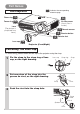
Power ON/OFF Turning On The Power WARNING • When the power is ON, a strong light is emitted. Do not look into the lens or vents of the projector. NOTE • Turn the power on/off in right order. Please power on the projector before the connected devices. Power off the projector after the connected devices. 1 Make sure that the power cord is firmly and correctly connected to the projector and outlet. POWER indicator TEMP POWER STANDBY/ON 2 When the lens cap is attached, remove the lens cap.
Power ON/OFF (continued) Selecting An Input Signal TEMP POWER 1 Using the projector’s control button STANDBY/ON Press the INPUT button. VIDEO INPUT MENU INPUT button As illustrated below, each time you press the INPUT button, the projector switches between its input signal ports. Select the signal you wish to project. RGB LAMP S-VIDEO AC IN COMPONENT VIDEO Selecting a RGB signal, using the remote control RGB button Press the RGB button.
Power ON/OFF (continued) Turning Off The Power NOTE • Turn the power on/off in right order. Please power on the projector before the connected devices. Power off the projector after the connected devices. 1 Press the STANDBY/ON button of the projector or the button of the remote control. The message “Power off?” will appear on the screen for approximately 5 seconds. POWER indicator 2 Press the STANDBY/ON button again while “Power off?” the message is visible.
Operating Adjusting The Volume 1 VIDEO RGB ASPECT SEARCH AUTO BLANK Press the VOLUME button. VOLUME As illustrated on the right, a dialog will appear on the screen to aid you in adjusting the volume. VOLUME VOLUME MAGNIFY ON MUTE 16 OFF FREEZE KEYSTONE POSITION MENU 2 / buttons to adjust the Press the VOLUME button again to close the dialog and complete this operation. (Even if you don't do anything, the dialog will automatically disappear after a few seconds.
Operating (continued) Adjusting The Position 1 RGB VIDEO SEARCH AUTO ASPECT Press the POSITION button. As illustrated on the right, a dialog will appear on the screen to aid you in adjusting the position. BLANK VOLUME MAGNIFY ON MUTE POSITION OFF FREEZE KEYSTONE POSITION POSITION MENU ENTER ESC RESET 2 , Use the the position. , , buttons to adjust When you want to initialize the position, press the RESET button during adjustment.
Operating (continued) Using The Automatic Adjustment Feature 1 VIDEO RGB ASPECT Press the AUTO button. AUTO SEARCH AUTO BLANK Automatic Adjustment for RGB Input VOLUME MAGNIFY Horizontal position (H POSITION), vertical position (V POSITION), clock phase (H PHASE) and horizontal size (H SIZE) are automatically adjusted. Make sure that the application window is set to its maximum size prior to attempting to use this feature. Dark pictures may still be incorrectly adjusted.
Operating (continued) Using The Magnify Feature VIDEO RGB ASPECT 1 Press the MAGNIFY (ON) button. 2 Press the POSITION button, then use the , , , buttons to select the area to zoom. Press the POSITION button again to finalize the zoom area. MAGNIFY ON The projector enters MAGNIFY mode. SEARCH AUTO BLANK VOLUME MAGNIFY ON MUTE OFF FREEZE KEYSTONE POSITION POSITION POSITION MENU ENTER ESC RESET 3 Use the level.
Operating (continued) Signal Searching 1 VIDEO RGB ASPECT SEARCH AUTO BLANK Press the SEARCH button. Cycle through input signals, displaying the images of retrieved signals. If no signal is found, returns to the signal that was selected before the search was begun. RGB VIDEO S-VIDEO SEARCH VOLUME MAGNIFY ON MUTE OFF COMPONENT VIDEO FREEZE KEYSTONE NOTE • May not function properly with some input signals. • The signal searching function takes about 10 seconds to display an image.
Multifunctional Settings Using The Menu Functions This projector has the following menus: MAIN, PICTURE-1, PICTURE-2, INPUT, AUTO, SCREEN, OPTION. Each of these menus is operated using the same methods. The basic operations of these menus are as follows. 1 VIDEO RGB ASPECT SEARCH AUTO Press the MENU button. The menu display appears on the screen. BLANK [ex. Adjusting VOLUME] 1. Press the MENU button.
Multifunctional Settings (continued) MAIN Menu With the MAIN menu, the items shown in the table below can be performed. Perform each operation in accordance with the instructions in the table below.
Multifunctional Settings (continued) PICTURE - 1 Menu With the PICTURE - 1 menu, the items shown in the Table below can be performed. Perform each operation in accordance with the instructions in the table below.
Multifunctional Settings (continued) PICTURE - 1 Menu (continued) Item Description MY MEMORY Load/Save a Setting: Selecting one from the following and then pressing the or the ENTER button performs each function. LOAD1 ⇔ LOAD2 ⇔ LOAD3 ⇔ LOAD4 ⇒ SAVE1 ⇔ SAVE2 ⇔ SAVE3 ⇔ SAVE4 • This projector has 4 memories called M1, M2, M3 and M4 for settings. Performing the SAVE1, SAVE2, SAVE3 or SAVE4 puts the current setting data on the memory whose number corresponds.
Multifunctional Settings (continued) PICTURE - 2 Menu With the PICTURE - 2 menu, the items shown in the table below can be performed. Perform each operation in accordance with the instructions in the table below. Item V POSITION H POSITION H PHASE H SIZE OVER SCAN RESET 20 142 31 1344 95 : SELECT Description V POSITION Adjust the Vertical Position: Up ⇔ Down • This item can be selected only at a RGB input.
Multifunctional Settings (continued) INPUT Menu With the INPUT menu, the items shown in the table below can be performed. Perform each operation in accordance with the instructions in the table below.
Multifunctional Settings (continued) INPUT Menu (continued) Description VIDEO NR Select a Noise Reduction Mode: HIGH ⇔ MIDDLE ⇔ LOW • This function performs only at a VIDEO input or a S-VIDEO input. At a VIDEO input of NTSC 3.58, this function performs only when the TURN OFF is selected under the 3D-YCS. • When the HIGH, the MIDDLE or the LOW is selected, the noise on screen is reduced according to each mode. • When this function is excessive, it may cause a certain degradation of the picture.
Multifunctional Settings (continued) AUTO Menu With the AUTO menu, the items shown in the table below can be performed. Perform each operation in accordance with the instructions in the table below. MENU MAIN PICTURE-1 PICTURE-2 INPUT AUTO SCREEN OPTION ADJUST POWER OFF SEARCH RESET 0 min TURN ON : SELECT Item Description ADJUST Automatically Adjust the Picture: Pressing the or the ENTER button performs this function.
Multifunctional Settings (continued) SCREEN Menu With the SCREEN menu, the items shown in the table below can be performed. Perform each operation in accordance with the instructions in the table below. MENU MAIN PICTURE-1 PICTURE-2 INPUT AUTO SCREEN OPTION BLACK BLANK TURN ON START UP MENU POSITION MESSAGE TURN ON RESET : SELECT Item Description BLANK Select a Blank Screen Color: BLUE ⇔ WHITE ⇔ BLACK • The blank screen of selected color is displayed by pressing the BLANK button.
Multifunctional Settings (continued) OPTION Menu With the OPTION menu, the items shown in the table below can be performed. Perform each operation in accordance with the instructions in the table below.
Lamp WARNING HIGH VOLTAGE HIGH TEMPERATURE HIGH PRESSURE The projector uses a high-pressure mercury glass lamp. The lamp can break with a loud bang, or burn out, if jolted or scratched, handled while hot, or worn over time. Note that each lamp has a different lifetime, and some may burst or burn out soon after you start using them. In addition, when the bulb bursts, it is possible for shards of glass to fly into the lamp housing, and for gas containing mercury to escape from the projector’s vent holes.
Lamp (continued) Replacing The Lamp WARNING • Please carefully read the “User’s Manual - Safety Guide”. CAUTION • Do not reset the lamp timer without replacing the lamp. • When you replace the lamp, please replace also the air filter. The air filter may be attached when you buy a replacement lamp for this projector. Please ask your dealer. If the indicators or a message prompts you to replace the lamp, replace the lamp as soon as possible.
Air Filter WARNING • Please carefully read the “User’s Manual - Safety Guide”. • Before replacing the air filter, make sure the power switch is off and the power cable is not plugged in. • Use the air filter of the specified type only. Type number: NJ08292 (sold separately) • Do not use the projector with the air filter and filter cover removed. The use without the air filter could result in damage. CAUTION • Do not reset the filter timer without cleaning or replacing the air filter.
Air Filter (continued) Replacing The Air Filter If the soiling will not come off the air filter, or it becomes damaged, then it needs to be replaced. Please replace the air filter as soon as possible. 1 Turn off the projector, and unplug the power cord. 2 Contact your local dealer to prepare a new air filter. Tell the dealer your air filter type number. 3 After making sure that the projector has cooled adequately, remove the filter cover.
Other Care WARNING • Please carefully read the “User’s Manual - Safety Guide”. • Before replacing the air filter, make sure the power switch is off and the power cable is not plugged in. ATTENTION • Do not use cleaners or chemicals other than those listed below, including benzene and paint thinner. • Do not use aerosols or sprays. • Do not polish or wipe with hard objects.
Troubleshooting Related Messages When the unit's power is ON, messages such as those shown below may be displayed. When any such message is displayed on the screen, please respond as described below. If the same message is displayed after the treatment, or if a message other than the following appears, please contact your dealer or service company. Message CHANGE THE LAMP AFTER REPLACING LAMP, RESET THE LAMP TIMER. (*1) Description Lamp usage time is approaching 2000 hours.
Troubleshooting (continued) Related Messages (continued) Message Description A note of precaution when cleaning the air filter. CLEAN THE AIR FILTER Please immediately turn the power OFF, and clean or change POWER OFF FIRST, the air filter by referring to the “Air Filter” section of this manual. THEN CLEAN THE AIR FILTER. After you have cleaned or changed the air filter, please be sure to reset the filter timer.
Troubleshooting (continued) Regarding The Indicator Lamps ATTENTION • When the interior portion has become overheated, for safety purposes, the power source is automatically turned off, and the indicator lamps may also be turned off. In such a case, press the “○” (power OFF) side of the main power switch, and wait at least 45 minutes. After the unit has sufficiently cooled down, please make confirmation of the attachment state of the lamp and lamp cover, and then turn the power on again.
Troubleshooting (continued) Regarding The Indicator Lamps (continued) POWER indicator Lighting or blinking in red LAMP indicator TEMP indicator Turned off The cooling fan is not operating. Turn the power OFF and wait at least 20 minutes. After the unit has sufficiently cooled down, Blinking in please make confirmation of the following item, and then red resent the power to ON.
Troubleshooting (continued) Phenomena That May Easily Be Mistaken For Machine Defects WARNING • Please carefully read the “User’s Manual - Safety Guide”. Never use the projector if abnormal operations such as smoke, strange odor, excessive sound, damaged casing or elements or cables, penetration of liquids or foreign matter, etc. should occur.
Troubleshooting (continued) Phenomena That May Easily Be Mistaken For Machine Defects (continued) Phenomenon Pictures appear dark. Cases not involving a machine defect, and Items to be confirmed Reference pages The brightness setting and/or contrast setting has not been properly adjusted. Perform picture adjustments by changing the BRIGHT and/or CONTRAST settings, etc. 23 The WHISPER mode is the current setting. Change (by releasing) from the WHISPER mode.
Specifications Item Specification Product name Liquid crystal panel Liquid crystal projector Panel size 1.4 cm (0.55 type) Drive system TFT active matrix Pixels 480,000 pixels (800 horizontal x 600 vertical) Lens Zoom lens F=1.6 ~ 1.8 f=16.8 ~ 20.1 mm Lamp 130W UHB Speaker 1.0W Power supply AC100 ~ 120V, 2.4A / AC220 ~ 240V, 1.1A Power consumption 220W Temperature range 0 ~ 35°C (Operating) Size 332 (W) x 92 (H) x 254 (D) mm (Not including protruding parts) Weight (mass) 2.
Projector CP-S210/CP-S210T/CP-S210F CP-S210W/CP-S210WT/CP-S210WF User's Manual - Operating Guide TECHNICAL In this section, the technical information about this projector is described. WARNING Before using, read the "User's Manual - Safety Guide" and these manuals to ensure correct usage through understanding. After reading, store them in a safe place for future reference. NOTE • The information in this manual is subject to change without notice.
TECHNICAL Signal Connectors VIDEO L - AUD I O - R 2 10 4 5 6 7 8 9 AUDIO S-VIDEO 1 RGB 3 CONTROL Y CB/PB CR/PR COMPONENT VIDEO Port Specification 1 RGB Video signal: RGB separate, Analog, 0.7 Vp-p, 75 Ω terminator (positive) H/V. sync. signal:TTL level (positive/negative) Composite sync. signal: TTL level D-sub 15-pin shrink jack 11 12 13 14 15 6 7 1 8 2 9 10 3 4 5 2 AUDIO (interlocked 1 port) 5 8 4 7 3 6 2 1 No. 6 7 Signal Ground Red Ground Green No.
Example Of Computer Signal Resolution H×V fH (kHz) fV (Hz) Rating Signal mode Display mode 720 × 400 37.9 85.0 VESA TEXT Zoom in 640 × 480 31.5 59.9 VESA 640 × 480 35.0 66.7 640 × 480 37.9 72.8 640 × 480 37.5 75.0 640 × 480 43.3 800 × 600 800 × 600 VGA (60Hz) Zoom in Mac13"mode Zoom in VESA VGA (72Hz) Zoom in VESA VGA (75Hz) Zoom in 85.0 VESA VGA (85Hz) Zoom in 35.2 56.3 VESA SVGA (56Hz) 37.9 60.3 VESA SVGA (60Hz) 800 × 600 48.1 72.
Initial Set Signals The following signals are used for the initial settings. The signal timing of some computer models may be different. In such case, refer to adjust the V.POSIT and H.POSIT of the menu. Back porch b Front porch d Display interval c Back porch b Front porch d Display interval c DATA DATA HSYNC VSYNC Sync a Computer / Signal 4 Sync a Horizontal signal timing (µs) TEXT a 2.0 b 3.0 c 20.3 d 1.
RS-232C Communication Connecting The Cable (1) Turn off the projector and the computer power supplies. (2) Connect the CONTROL port of the projector with a RS-232C port of the computer by a RS232C cable. Use the cable that fulfills the specification shown in the following figure. (3) Turn on the computer power supply and after the computer has started up, turn on the projector power supply.
RS-232C Communication (continued) Requesting projector status (Get command) (1) Send the request code Header + Command data (‘02H’+‘00H’+ type (2 bytes)+‘00H’+‘00H’) from the computer to the projector. (2) The projector returns the response code ‘1DH’+ data (2 bytes) to the computer. Changing the projector settings (Set command) (1) Send the setting code Header + Command data (‘01H’+‘00H’+ type (2 bytes) + setting code (2 bytes)) from the computer to the projector.
RS-232C Communication (continued) Command Data Chart Names Operation type Command data Header Type Setting code Get BE EF 03 06 00 B9 D3 02 00 07 20 00 00 Keystone Increment Decrement BE EF BE EF 03 03 06 00 06 00 DF D3 0E D2 04 00 05 00 07 20 07 20 00 00 00 00 Keystone Reset Execute BE EF 03 06 00 08 D0 06 00 0C 70 00 00 Get BE EF 03 06 00 89 D2 02 00 03 20 00 00 Increment BE EF 03 06 00 EF D2 04 00 03 20 00 00 Decrement BE EF 03 06 00 3E D3 05 00 03 20
RS-232C Communication (continued) Command Data Chart (continued) Names Language Operation type Set Type Setting code English BE EF 03 06 00 F7 D3 01 00 05 30 00 00 FRANÇAIS BE EF 03 06 00 67 D2 01 00 05 30 01 00 Deutsch BE EF 03 06 00 97 D2 01 00 05 30 02 00 ESPAÑOL BE EF 03 06 00 07 D3 01 00 05 30 03 00 Italiano BE EF 03 06 00 37 D1 01 00 05 30 04 00 Norsk BE EF 03 06 00 A7 D0 01 00 05 30 05 00 Nederlands PORTUGUÊS BE EF 03 06 00 57 D0 01 00 05 30
RS-232C Communication (continued) Command Data Chart (continued) Names Operation type Command data Header Type Setting code 50 BE EF 03 06 00 EF F6 01 00 B3 30 05 00 60 BE EF 03 06 00 7F F7 01 00 B3 30 04 00 70 BE EF 03 06 00 4F F5 01 00 B3 30 03 00 80 BE EF 03 06 00 DF F4 01 00 B3 30 02 00 90 BE EF 03 06 00 2F F4 01 00 B3 30 01 00 100 BE EF 03 06 00 BF F5 01 00 B3 30 00 00 Get BE EF 03 06 00 8C F5 02 00 B3 30 00 00 Get BE EF 03 06 00 01 D2
RS-232C Communication (continued) Command Data Chart (continued) Names Operation type Get V Position Increment Decrement V Position Reset Execute Get H Position Increment Decrement H Position Reset Execute Get H Phase Increment Decrement Get H Size Increment Decrement H Size Reset Execute Get Over Scan Increment Decrement Over Scan Reset Execute AUTO RGB Set SMPTE240 Color Space REC709 REC601 Get COMPONENT Set Component SCART RGB Get AUTO NTSC PAL SECAM Set Video Format NTSC 4.
RS-232C Communication (continued) Command Data Chart (continued) Names Video NR Progressive S2-Aspect Operation type Set Set Set Auto Adjust Auto off Auto Search Blank Color Blank on/off Startup Set Set Set Set Menu Position V LOW MIDDLE HIGH Get Turn off TV Film Get TURN OFF TURN ON Get Execute Get Increment Decrement TURN OFF TURN ON Get Blue White Black Get TURN OFF TURN ON Get TURN ON TURN OFF Get Get Increment Decrement Command data Header CRC Action Type Setting code BE EF BE
RS-232C Communication (continued) Command Data Chart (continued) Names Operation type Volume MUTE Screen type Set Set Lamp Time Lamp Time Reset Filter Time Filter Time Reset Magnify Freeze Set Set Get Increment Decrement TURN ON TURN OFF Get 4:3 16:9- Top 16:9- Center 16:9- Bottom Get Get Execute Get Execute Get Increment Decrement Normal Freeze Get TURN OFF TURN ON Command data Header BE EF BE EF BE EF BE EF BE EF BE EF BE EF BE EF BE EF BE EF BE EF BE EF BE EF BE EF BE EF BE EF BE EF BE EF BE