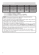
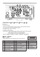
Projector CP-X8150/CP-X8160/ CP-WX8240/CP-WX8255/ CP-SX8350/CP-WU8440/CP-WU8450 User's Manual (detailed) Operating Guide – Technical Example of computer signal Resolution (H x V) H. frequency (kHz) V. frequency (Hz) Rating Signal mode 37.9 31.5 37.9 37.5 43.3 35.2 37.9 48.1 46.9 53.7 49.7 48.4 56.5 60.0 68.7 67.5 47.7 49.7 60.0 64.0 80.0 55.
Example of computer signal Resolution (H x V) H. frequency (kHz) V. frequency (Hz) Rating Signal mode 1280 x 1024 1400 x 1050 1680 x 1050 1600 x 1200 91.1 65.2 65.3 75.0 85.0 60.0 60.0 60.0 VESA VESA VESA VESA *4 1920 x 1200 74.0 60.0 VESA SXGA (85Hz) SXGA+ (60Hz) WSXGA+ (60Hz) UXGA (60Hz) W-UXGA (60Hz) Reduced Blanking *1 *2 *3 *1 *1) Supported except for HDMI input. *2) Only for CP-X8150, CP-X8160 and CP-SX8350. *3) Only for CP-WX8240, CP-WX8255, CP-WU8440 and CP-WU8450.
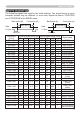
Initial set signals Initial set signals The following signals are used for the initial settings. The signal timing of some computer models may be different. In such case, adjust the items V POSITION and H POSITION in the IMAGE menu. Back porch (B) Front porch (D) Active video (C) Data H. Sync.
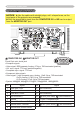
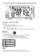
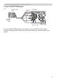
Connection to the ports Connection to the ports NOTICE ►Use the cables with straight plugs, not L-shaped ones, as the input ports of the projector are recessed. ►Only the signal that is input from the COMPUTER IN1 or IN2 can be output from the MONITOR OUT port. A B A COMPUTER IN1, B MONITOR OUT ⑪⑫⑬⑭⑮ ⑥⑦⑧⑨⑩ ①②③④⑤ D-sub 15pin mini shrink jack • Video signal: RGB separate, Analog, 0.7Vp-p, 75Ω terminated (positive) • H/V. sync. signal: TTL level (positive/negative) • Composite sync.
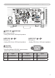
Connection to the ports (continued) H I C D F E G COMPUTER IN2 C G/Y, D B/Cb/Pb, E R/Cr/Pr, F H, G V BNC jack x5 • Video signal: RGB separate, Analog, 0.7Vp-p, 75Ω terminated (positive) • H/V. sync. signal: TTL level (positive/negative) • Composite sync. signal: TTL level • Video signal: Y with composite sync, Analog, 1.0±0.1Vp-p, 75Ω terminated Cb/Pb, Analog, 0.7±0.1Vp-p, 75Ω terminated Cr/Pr, Analog, 0.7±0.
Connection to the ports (continued) N M L K J COMPONENT J Y, K Cb/Pb, L Cr/Pr RCA jack x3 ① ③ • Component video signal, Analog: -Y with composite sync, 1.0±0.1Vp-p, 75Ω terminated -Cb/Pb, 0.7±0.1Vp-p, 75Ω terminated -Cr/Pr, 0.7±0.1Vp-p 75Ω terminated • System: 480i@60, 480p@60, 576i@50, 720p@50/60, 1080i@50/60, 1080p@50/60 ② ④ 2 4 ④ ② M S-VIDEO 1 3 ③ ① Mini DIN 4pin jack • S-video signal, Analog: -Brightness signal with composite sync, 1.0±0.1Vp-p, 75Ω terminated -Color signal, 0.
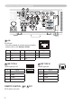
Connection to the ports (continued) U S Q T R O P O AUDIO IN1, P AUDIO IN2 Ø3.5 stereo mini jack • Analog, 500 mVrms, 47kΩ input impedance AUDIO IN3 Q L, R R AUDIO OUT S L, T R RCA jack x2 RCA jack x2 • Analog, 500 mVrms, 47kΩ input impedance • Analog, 500 mVrms, 1kΩ output impedance U CONTROL D-sub 9pin plug ① ② ③ ④ ⑤ ⑨ ⑧ ⑦ ⑥ ⑥ ⑦ ⑧ ⑨ ⑤ ④ ③ ② ① * About the details of RS-232C communication, please refer to the next section.
Connection to the ports (continued) X W V Y Z V LAN RJ-45 jack Pin 1 Signal TX+ Pin 4 Signal - 8 - TX- 5 - RX+ 6 RX- W USB TYPE A Pin Signal ④ ③② ① ④ ③② ① X USB TYPE B USB B type jack Pin ① ②③ ④ Signal +5V 1 +5V 2 - Data 2 - Data 3 + Data 3 + Data 4 Ground 4 Ground Ø3.
Connection to the ports (continued) To input SCART RGB signal; ex. SCART cable (plug) Audio L RCA plugs Audio R Video R SCART connector (jack) B G To input SCART RGB signal to the projector, use a SCART to RCA cable. Connect the plugs refer to above ex. For more reference, please consult your dealer.
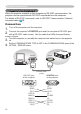
RS-232C Communication RS-232C Communication When the projector connects to the computer by RS-232C communication, the projector can be controlled with RS-232C commands from the computer. For details of RS-232C commands, refer to RS-232C Communication / Network command table (&19). Connection 1. Turn off the projector and the computer. the projector's CONTROL port and the computer's RS-232C port 2. Connect with a RS-232C cable (cross).
RS-232C Communication (continued) Communicaion settings 1. Protocol 19200bps, 8N1 2. Command format ("h" shows hexadecimal) Byte Number 0 1 Command Action 2 3 4 5 6 7 8 9 Header Header code Packet L H 10 11 12 Data Data size CRC flag Action Type Setting code L L L L L H H H H H Change setting to desired value [(cL)(cH)] by [(bL)(bH)]. (aL) (aH) 01h 00h (bL) (bH) (cL) (cH) Read projector internal setup value [(bL) (bH)] .
RS-232C Communication (continued) 3. Response code / Error code ("h" shows hexadecimal) (1) ACK reply: 06h When the projector receives the Set, Increment, Decrement or Execute command correctly, the projector changes the setting data for the specified item by [Type], and it returns the code. (2) NAK reply: 15h When the projector cannot understand the received command, the projector returns the error code. In such a case, check the sending code and send the same command again.
Command Control via the Network Command Control via the Network When the projector connects network, the projector can be controlled with RS232C commands from the computer with web browser. For details of RS-232C commands, refer to RS-232C Communication / Network command table (&19). NOTE • If data is transferred via wireless and wired LAN at the same time, the projector may not be able to process the data correctly. Connection Turn off the projector and the computer. 1.
Command Control via the Network Communicaion Port The following two ports are assigned for the command control. TCP #23 TCP #9715 Configure the following items form a web browser when command control is used. Port Settings Network Control Port1 (Port: 23) Port open Click the [Enable] check box to open [Network Control Port1 (Port: 23)] to use TCP #23. Default setting is “Enable”. Authentication Click the [Enable] check box for the [Authentication] setting when authentication is required.
Command Control via the Network (continued) Command control settings [TCP #23] 1. Command format Same as RS-232C communication, refer to RS-232C Communicaton command format. 2. Response code / Error code ("h" shows hexadecimal) Four of the response / error code used for TCP#23 are the same as RS-232C Communication (1)~(4). One authentication error reply (5) is added. (1) ACK reply : 06h Refer to RS-232C communication (&12). (2) NAK reply : 15h Refer to RS-232C communication (&12).
Command Control via the Network (continued) 2. Response code / Error code ("h" shows hexadecimal) The connection ID is attached for the TCP#23's response / error codes are used. The connection ID is same as the sending command format.
Network Bridge Communication Network Bridge Communication This projector is equipped with NETWORK BRIDGE function. When the projector connects to the computer by wired or wireles LAN communicaton, an external device that is connected with this projector by RS232C communication can be controlled from the computer as a network terminal. For details, see the 6. Network Bridge function in the Network Guide.
Network Bridge Communication Communication settings For communication setting, use the COMMUNICATION menu in the OPTION SERVICE menu Item Condition BAUD RATE 4800bps / 9600bps / 19200bps / 38400bps Data length 8 bit (fixed) PARITY NONE/ODD/EVEN Start bit 1 bit (fixed) Stop bit 1 bit (fixed) Transmission method HALF-DUPLEX/FULL-DUPLEX NOTE • For connecting the projector to your devices, please read the manual for each devices, and connect them correctly with suitable cables.
RS-232C Communication / Network command table RS-232C Communication / Network command table Names Operation Type Set Power Input Source Set Error Status FOCUS ZOOM LENS SHIFT - V LENS SHIFT - H LENS SHIFT CENTERING LENS MEMORY Set INDEX Header Turn off Turn on BE EF 03 BE EF 03 BE EF 03 [Example return] Get 00 00 [Off] COMPUTER IN1 BE EF 03 COMPUTER IN2 BE EF 03 LAN BE EF 03 USB TYPE A BE EF 03 USB TYPE B BE EF 03 HDMI 1 BE EF 03 HDMI 2 BE EF 03 COMPONENT BE EF 03 S-VIDEO BE EF 03 VIDEO BE EF 03 G
RS-232C Communication / Network command table (continued) Names Operation Type LENS MEMORY LENS SHIFT - V Get BE EF 03 06 00 LENS MEMORY LENS SHIFT - H Get BE EF 03 LENS MEMORY LENS TYPE Get BE EF BE BE BE BE BE BE BE BE BE BE BE BE BE BE BE BE BE BE BE BE BE BE BE BE BE BE BE MAGNIFY MAGNIFY Position H MAGNIFY Position V FREEZE SHADE PICTURE MODE BRIGHTNESS Set Set Set Get Increment Decrement Get Increment Decrement Get Increment Decrement NORMAL FREEZE Get OFF ON Get NORMAL CINEMA DYNA
RS-232C Communication / Network command table (continued) Names GAMMA User GAMMA COLOR TEMP Pattern User GAMMA Point 1 Operation Type 1 DEFAULT 1 CUSTOM 2 DEFAULT 2 CUSTOM 3 DEFAULT 3 CUSTOM 4 DEFAULT Set 4 CUSTOM 5 DEFAULT 5 CUSTOM 6 DEFAULT 6 CUSTOM 7 DEFAULT 7 CUSTOM Get Off 9 steps gray scale Set 15 steps gray scale Ramp Get Get Increment Decrement Header BE BE BE BE BE BE BE BE BE BE BE BE BE BE BE BE BE BE BE BE BE BE BE CRC EF EF EF EF EF EF EF EF EF EF EF EF EF EF EF EF EF EF EF EF EF EF EF 0
RS-232C Communication / Network command table (continued) Names Operation Type User GAMMA Point 6 Get Increment Decrement BE EF BE EF BE EF 03 03 03 06 00 06 00 06 00 User GAMMA Point 6 Reset Execute BE EF 03 User GAMMA Point 7 Get Increment Decrement BE EF BE EF BE EF User GAMMA Point 7 Reset Execute User GAMMA Point 8 User GAMMA Point 8 Reset COLOR TEMP COLOR TEMP GAIN R Set Header CRC Command Data Action Type Setting code C4 FE A2 FE 73 FF 02 00 04 00 05 00 95 30 95 30 95 30 0
RS-232C Communication / Network command table (continued) Names Operation Type Header COLOR TEMP OFFSET R Get Increment Decrement BE EF BE EF BE EF 03 03 03 06 00 06 00 06 00 COLOR TEMP OFFSET R Reset Execute BE EF 03 COLOR TEMP OFFSET G Get Increment Decrement BE EF BE EF BE EF COLOR TEMP OFFSET G Reset Execute COLOR TEMP OFFSET B CRC Command Data Action Type Setting code 04 F5 62 F5 B3 F4 02 00 04 00 05 00 B5 30 B5 30 B5 30 00 00 00 00 00 00 06 00 40 C5 06 00 4A 70 00 00 03
RS-232C Communication / Network command table (continued) Names Operation Type OVER SCAN Get Increment Decrement BE EF BE EF BE EF 03 03 03 06 00 06 00 06 00 OVER SCAN Reset Execute BE EF 03 V POSITION Get Increment Decrement BE EF BE EF BE EF V POSITION Reset Execute H POSITION H POSITION Reset H SIZE CRC Command Data Action Type Setting code 91 70 F7 70 26 71 02 00 04 00 05 00 09 22 09 22 09 22 00 00 00 00 00 00 06 00 EC D9 06 00 27 70 00 00 03 03 03 06 00 06 00 06 00 0D 8
RS-232C Communication / Network command table (continued) Names Operation Type S-VIDEO FORMAT Set C-VIDEO FORMAT Set HDMI 1 FORMAT Set HDMI 2 FORMAT Set HDMI 1 RANGE HDMI 2 RANGE COMPUTER IN1 COMPUTER IN2 Set Set Set Set FRAME LOCK - Set COMPUTER IN1 FRAME LOCK - Set COMPUTER IN2 FRAME LOCK - Set HDMI 1 FRAME LOCK - Set HDMI 2 (continued on next page) AUTO NTSC PAL SECAM NTSC4.43 M-PAL N-PAL Get AUTO NTSC PAL SECAM NTSC4.
RS-232C Communication / Network command table (continued) Names Operation Type AUTO KEYSTONE V EXECUTE Execute BE EF 03 06 00 KEYSTONE V Get Increment Decrement BE EF BE EF BE EF 03 03 03 06 00 06 00 06 00 KEYSTONE V Reset Execute BE EF 03 KEYSTONE H Get Increment Decrement BE EF BE EF BE EF 03 03 03 KEYSTONE H Reset Execute BE EF 03 BE BE BE BE BE BE BE BE BE BE BE BE BE BE BE BE BE BE BE BE BE BE BE BE BE BE BE EF EF EF EF EF EF EF EF EF EF EF EF EF EF EF EF EF EF EF EF EF EF EF E
RS-232C Communication / Network command table (continued) Names Operation Type (*) PERFECT FIT Left Side Distortion Get Increment Decrement Get Increment Decrement Get Increment Decrement Get Increment Decrement Get Increment Decrement Get Increment Decrement (*) PERFECT FIT Right Side Distortion (*) PERFECT FIT Distortion Position V (*) PERFECT FIT Top Side Distortion (*) PERFECT FIT Bottom Side Distortion (*) PERFECT FIT Distortion Position H Header BE BE BE BE BE BE BE BE BE BE BE BE BE BE BE BE BE
RS-232C Communication / Network command table (continued) Names STANDBY MODE Operation Type Set MONITOR OUT - Set COMPUTER IN1 MONITOR OUT - Set COMPUTER IN2 MONITOR OUT - Set LAN MONITOR OUT- Set USB TYPE A MONITOR OUT - Set USB TYPE B MONITOR OUT Set - HDMI 1 MONITOR OUT Set - HDMI 2 MONITOR OUT Set - COMPONENT MONITOR OUT Set - S-VIDEO MONITOR OUT Set - VIDEO MONITOR OUT Set - STANDBY 28 NORMAL SAVING Get COMPUTER IN1 OFF Get COMPUTER IN2 OFF Get COMPUTER IN1 COMPUTER IN2 OFF Get COMPUTER IN1 COMPUTE
RS-232C Communication / Network command table (continued) Names Operation Type VOLUME COMPUTER IN1 VOLUME COMPUTER IN2 VOLUME - LAN VOLUME USB TYPE A VOLUME USB TYPE B VOLUME HDMI 1 VOLUME HDMI 2 VOLUME COMPONENT VOLUME S-VIDEO VOLUME VIDEO VOLUME STANDBY VOLUME - ALL MUTE SPEAKER Set Set (continued on next page) Get Increment Decrement Get Increment Decrement Get Increment Decrement Get Increment Decrement Get Increment Decrement Get Increment Decrement Get Increment Decrement Get Increment Decrement
RS-232C Communication RS-232C Communication / Network command / Network tablecommand (continued) table (continued) Names Operation Type AUDIO Set SOURCE COMPUTER IN1 AUDIO Set SOURCE COMPUTER IN2 AUDIO SOURCE LAN AUDIO SOURCE USB TYPE A AUDIO SOURCE USB TYPE B AUDIO SOURCE HDMI 1 AUDIO SOURCE HDMI 2 AUDIO SOURCE COMPONENT 30 Set Set Set Set Set Set AUDIO IN1 AUDIO IN2 AUDIO IN3 OFF Get AUDIO IN1 AUDIO IN2 AUDIO IN3 OFF Get AUDIO IN1 AUDIO IN2 AUDIO IN3 AUDIO LAN OFF Get AUDIO IN1 AUDIO IN2
RS-232C Communication RS-232C Communication / Network command / Network tablecommand (continued) table (continued) Names AUDIO SOURCE S-VIDEO AUDIO SOURCE VIDEO AUDIO SOURCE AUDIO OUT STANDBY LAN SOUND ENABLE USB TYPE A SOUND ENABLE USB TYPE B SOUND ENABLE HDMI 1 AUDIO HDMI 2 AUDIO LANGUAGE Operation Type Set Set Set Set Set Set Set Set Set (continued on next page) Header CRC Command Data Action AUDIO IN1 BE EF 03 06 00 D6 DD 01 AUDIO IN2 BE EF 03 06 00 26 DD 01 AUDIO IN3 BE EF 03 06 00 B6
RS-232C Communication / Network command table (continued) Names LANGUAGE MENU POSITION V Operation Type Header CRC Command Data Action TÜRKÇE BE EF 03 06 00 07 D6 01 DANSK BE EF 03 06 00 A7 DF 01 ČESKY BE EF 03 06 00 57 DF 01 MAGYAR BE EF 03 06 00 C7 DE 01 ROMÂNĂ BE EF 03 06 00 F7 DC 01 SLOVENSKI BE EF 03 06 00 67 DD 01 HRVATSKI BE EF 03 06 00 97 DD 01 ΕΛΛΗΝΙΚΑ BE EF 03 06 00 07 DC 01 Set LIETUVIŲ BE EF 03 06 00 F7 D9 01 EESTI BE EF 03 06 00 67 D8 01 LATVIEŠU BE EF 03 06 00 97 D8 01 BE EF 03 06 00 07
RS-232C Communication / Network command table (continued) Names TEMPLATE TEMPLATE On/Off C. C. - DISPLAY C. C. - MODE C. C.
RS-232C Communication / Network command table (continued) Names Operation Type SOURCE SKIP - Set COMPONENT SOURCE SKIP - Set S- VIDEO SOURCE SKIP - Set VIDEO AUTO SEARCH Set AUTO KEYSTONE Set DIRECT POWER ON Set AUTO POWER OFF SHADE TIMER USB TYPE B LAMP TIME Lower Bytes LAMP TIME Higher Bytes LAMP TIME Reset FILTER TIME Lower Bytes FILTER TIME Higher Bytes FILTER TIME Reset 34 Set Set NORMAL SKIP Get NORMAL SKIP Get NORMAL SKIP Get OFF ON Get OFF ON Get OFF ON Get Get Increment Decrement 1h 3h
RS-232C Communication / Network command table (continued) Names MY BUTTON-1 MY BUTTON-2 MY BUTTON-3 Operation Type SLIDESHOW MY IMAGE MESSENGER SHADE INFORMATION AUTO KEYSTONE V MY MEMORY Set ACTIVE IRIS PICTURE MODE FILTER RESET TEMPLATE MUTE RESOLUTION ECO MODE Get SLIDESHOW MY IMAGE MESSENGER SHADE INFORMATION AUTO KEYSTONE V MY MEMORY Set ACTIVE IRIS PICTURE MODE FILTER RESET TEMPLATE MUTE RESOLUTION ECO MODE Get SLIDESHOW MY IMAGE MESSENGER SHADE INFORMATION AUTO KEYSTONE V MY MEMORY Set ACTIVE IRI
RS-232C Communication / Network command table (continued) Names MY BUTTON-4 Operation Type Set Set REMOTE RECEIV. FRONT Set REMOTE RECEIV. REAR REMOTE ID Set REMOTE FREQ. Set NORMAL REMOTE FREQ.
PJLink command PJLink command Commands Control Description POWR Power Contorol POWR ? Power Status inquiry INPT Input Source selection INPT ? Input Source inquiry AVMT AV Mute AVMT ? AV Mute inquiry (continued on next page) Parameter or Response 0 = Standby 1 = Power On 0 = Standby 1 = Power On 2 = Cool Down 11 = COMPUTER IN 1 12 = COMPUTER IN 2 21 = COMPONENT 22 = S-VIDEO 23 = VIDEO 31 = HDMI 1 33 = HDMI 2 41 = USB TYPE A 51 = LAN 52 = USB TYPE B 11 = COMPUTER IN 1 12 = COMPUTER IN 2 21 = C
PJLink command (continued) Commands ERST ? Control Description Error Status inquiry LAMP ? Lamp Status inquiry INST ? Input Source List inquiry NAME ? Projector Name inquiry INF1 ? Manufucturer's Name inquiry INF2 ? INFO ? CLSS ? Parameter or Response 1st byte: Refers to Fan error; one of 0 to 2 2nd byte: Refers to Lamp error; one of 0 to 2 3rd byte: Refers to Temptrature error; one of 0 to 2 4th byte: Refers to Cover error; one of 0 to 2 5th byte: Refers to Filter error; one of 0 to 2 6th b