LCD Projector CP-X880/CP-X885 USER'S MANUAL Vol.2 (Extended) Thank you for purchasing this projector. WARNING • Please read the accompanying manual “SAFETY INSTRUCTIONS” and this “USER'S MANUAL” thoroughly to ensure correct usage through understanding. After reading, store this instruction manual in a safe place for future reference. NOTE • The information in this manual is subject to change without notice.
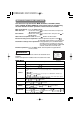
MULTIFUNCTIONAL SETTINGS This device has 8 separate menus: MAIN, PICTURE-1, PICTURE-2, INPUT, AUTO, SCREEN, OPTION, WIRELESS. Each of these menus is operated using the same methods. The basic operations of these menus are as follows. Menu screen display : Press the MENU button. Menu selection : Use the lever switch to select a menu name, then press the or ENTER button. to select an item, then press the or Item selection : Use the lever switch ENTER button.
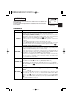
MENU MAIN PICTURE-1 PICTURE-2 INPUT AUTO SCREEN OPTION WIRELESS : SELECT PICTURE-1 Menu With the PICTURE-1 menu, the five items shown in the Table below can be performed. Perform each operation in accordance with the instructions in the Table.
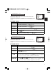
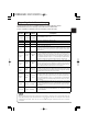
MULTIFUNCTIONAL SETTINGS (continued) INPUT Menu The three Input menu items listed in the table below can be manipulated. For RGB input, the reception signal’s horizontal and vertical frequency is displayed on the initial menu screen. Use the table below as a guide for operation. MENU MAIN PICTURE-1 PICTURE-2 INPUT AUTO SCREEN OPTION WIRELESS : SELECT BNC VIDEO HDTV SYNC ON G P. IN P. INPUT P. IN P.
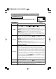
AUTO Menu With the AUTO menu, the four items shown in the Table below can be performed. Please perform each operation in accordance with the instructions in the Table. MENU MAIN PICTURE-1 PICTURE-2 INPUT AUTO SCREEN OPTION WIRELESS : SELECT ADJUST KEYSTONE POWER OFF ONE TOUCH EXECUTE Example : AUTO Menu (ADJUST) AUTO Menu Item Description ADJUST Auto Adjust (for RGB): Automatically adjusts H POSITION, V POSITION, H PHASE, and H SIZE. Use this function with the maximum window size.
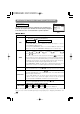
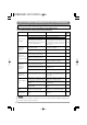
MULTIFUNCTIONAL SETTINGS (continued) SCREEN Menu With the SCREEN menu, the five items shown in the Table below can be performed. Please perform each operation in accordance with the instructions in the Table. BLANK START UP MyScreen MyScreen Size MyScreen Lock MyScreen ORIGINAL Example : SCREEN Menu (BLANK) SCREEN Menu Item Description BLANK Selection of BLANK Screen: MyScreen ORIGINAL . . . . . . The BLANK Screen may be voluntarily selected.
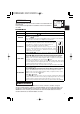
OPTION Menu With the OPTION menu, the five items shown in the Table below can be performed. Please perform each operation in accordance with the instructions in the Table. OPTION Menu Item MENU MAIN PICTURE-1 PICTURE-2 INPUT AUTO SCREEN OPTION WIRELESS : SELECT VOLUME WHISPER IR REMOTE LAMP TIME FILTER TIME 12 Example : OPTION Menu (VOLUME) Description VOLUME Adjust Volume: High WHISPER Select WHISPER Mode: NORMAL WHISPER When WHISPER is selected the WHISPER mode is activated.
WHAT TO DO WHEN YOU THINK A MACHINE DEFECT HAS OCCURRED Related Messages When the unit's power is ON, messages such as those shown below may be displayed. When any such message is displayed on the screen, please respond as described below. Message CHANGE THE LAMP AFTER REPLACING LAMP, RESET THE LAMP TIMER. (Note 1) Description Lamp usage time is approaching 2,000 hours. (Note 2) Preparation of a new lamp, and an early lamp change, is recommended.
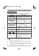
Regarding the Indicator Lamps Lighting and flashing of the POWER indicator, the LAMP indicator, and the TEMP indicator have the meanings as described in the Table below. Please respond in accordance with the instructions within the Table. POWER indicator LAMP indicator TEMP indicator The orange Turned OFF Turned OFF lamp is lighted (Not lighted) (Not lighted) Description The STANDBY mode is set Flashing of the green lamp Turned OFF Turned OFF The unit is warming up. Please wait.
WHAT TO DO WHEN YOU THINK A MACHINE DEFECT HAS OCCURRED (continued) Phenomena That May Easily Be Mistaken for Machine Defects Before requesting repair, check in accordance with the following chart. If the situation cannot be corrected, then contact your dealer. Phenomenon Cases not involving a machine defect Items to be confirmed Reference Page(s) The main power source is not ON. Turn on the main power. The electrical power cord is not plugged in. The input changeover settings are mismatched.
SPECIFICATIONS NOTE • This specifications are subject to change without notice. Item Product name Liquid crystal panel Specification Liquid crystal projector Panel size 2.5 cm (0.99 type) Drive system TFT active matrix Pixels 786,432 pixels (1024 horizontal x 768 vertical) Lens Zoom lens F=1.7 ~ 2.4 f=30.5 ~ 45.8 mm Lamp 275 W UHB Speaker 1.0W+1.0W (Stereo) Power supply AC100 ~ 120V, 4.7A / AC220 ~ 240V, 2.
WARRANTY AND AFTER-SERVICE If a problem occurs with the equipment, first refer to the 8 “WHAT TO DO WHEN YOU THINK A MACHINE DEFECT HAS OCCURRED” section and run through the suggested checks. If this does not resolve the problem contact your dealer or service company. They will tell you what warranty condition is applied.
TECHNICAL SIGNAL CONNECTOR PIN ASSIGNMENT RGB IN [1]/[2] RGB OUT S-VIDEO D-sub 15-pin Shrink Pin No 1 2 3 4 5 6 7 8 Signal Video input Red Video input Green Video input Blue Ground Ground Red Ground Green Ground Blue Mini Din 4-pin Pin No Signal 9 10 Ground 11 RGB IN [1]: SDA (DDC) 12 RGB IN [2]: RGB OUT : 13 H. sync./ Composite sync.
EXAMPLE OF COMPUTER SIGNAL Resolution H×V fH (kHz) fV (Hz) Rating Signal mode 720 × 400 37.9 85.0 VESA 640 × 480 31.5 59.9 VESA 640 × 480 35.0 66.7 640 × 480 37.9 72.8 640 × 480 37.5 75.0 640 × 480 43.3 800 × 600 800 × 600 Display mode CP-X880 CP-X885 TEXT Zoom in Zoom in VGA (60Hz) Zoom in Zoom in Mac13"mode Zoom in Zoom in VESA VGA (72Hz) Zoom in Zoom in VESA VGA (75Hz) Zoom in Zoom in 85.0 VESA VGA (85Hz) Zoom in Zoom in 35.2 56.
INITIAL SET SIGNALS The following signals are used for the initial settings. The signal timing of some computer models may be different. In such case, refer to adjust the V.POSIT and H.POSIT of the menu. Back porch b Front porch d Display interval c Back porch b Front porch d Display interval c DATA DATA HSYNC VSYNC Sync a Computer / Signal Sync a Horizontal signal timing (µs) TEXT a 2.0 b 3.0 c 20.3 d 1.
CONNECTION TO THE MOUSE CONTROL Projector ADB Mouse DATA CONTROL Terminal D-sub 15-pin shrink jack RTS 2 3 4 5 6 7 8 9 10 11 12 13 14 15 1 +5V GND Serial Mouse 1 2 3 4 SEL0 RTS D-sub 15-pin shrink jack 1 2 3 4 5 7 8 9 10 11 12 13 14 15 GND TD ADB (POWER ON) +5V GND Mouse jack Mini DIN 4-pin 3 4 1 2 Projector CONTROL Terminal 6 Computer 1 2 3 4 5 6 7 8 9 10 11 12 13 14 15 Computer 1 2 3 4 5 6 7 8 9 10 11 12 13 14 15 CD RD TD DTR GND DSR RTS CTS RI 1 2 3 4 5 6 7 8 9 Mouse jack D-sub
RS-232C COMMUNICATION (1) Turn off the projector and computer power supplies, and connect with the RS-232C adapter via the RS-232C cable. (2) Turn on the computer power supply and after the computer has started up, turn on the projector power supply.
RS-232C COMMUNICATION (continued) Requesting projector status (Get command) (1) Send the request code Header + Command data (‘02H’+‘00H’+ type (2 bytes) +‘00H’+‘00H’) from the computer to the projector. (2) The projector returns the response code ‘1DH’+ data (2 bytes) to the computer. Changing the projector settings (Set command) (1) Send the setting code Header + Command data (‘01H’+‘00H’+ type (2 bytes) + setting code (2 bytes)) from the computer to the projector.
Command data chart Names Operation type Command data Header CRC Action Type Setting code Blue BE EF 03 06 00 CB D3 01 00 00 30 03 00 White BE EF 03 06 00 6B D0 01 00 00 30 05 00 Black BE EF 03 06 00 9B D0 01 00 00 30 06 00 MyScreen BE EF 03 06 00 FB CA 01 00 00 30 20 00 ORIGNAL BE EF 03 06 00 FB E2 01 00 00 30 40 00 Get BE EF 03 06 00 08 D3 02 00 00 30 00 00 Normal BE EF 03 06 00 C7 D2 01 00 01 30 00 00 H Inverse BE EF 03 06 00 57 D3 01 00
Command data chart (continued) Names Operation type H.Position Reset Execute BE EF 03 H.
Names Operation type Command data Header CRC Color Balance B Keystone_V Keystone_H Aspect Picture Position at 16 : 9 or Small Get Increment Decrement Get Increment Decrement Get Increment Decrement 4:3 Set 16:9 Small Get Set Default Bottom Top Get Action Type Setting code BE EF BE EF BE EF 03 03 03 06 00 06 00 06 00 45 D2 23 D2 F2 D3 02 00 04 00 05 00 06 20 06 20 06 20 00 00 00 00 00 00 BE BE BE BE BE BE BE BE BE BE EF EF EF EF EF EF EF EF EF EF 03 03 03 03 03 03 03 03 03 03 06 06 06
Command data chart (continued) Names Sync on G Operation type Set Type Setting code off BE EF 03 06 00 CB D0 01 00 08 30 01 00 on BE EF BE EF 03 03 06 00 06 00 5B D1 68 D1 01 00 02 00 08 30 08 30 00 00 00 00 off Get CRC Action BE EF 03 06 00 FE 22 01 00 00 23 00 00 Large Small Get BE EF BE EF BE EF 03 03 03 06 00 06 00 06 00 6E 23 9E 23 CD 22 01 00 01 00 02 00 00 23 00 23 00 23 01 00 02 00 00 00 Upper left BE EF 03 06 00 02 23 01 00 01 23 00 00 Upper right BE
00CP-X885WBasic-四 02.10.7 6:55 PM ページ1 Hitachi America, Ltd. Hitachi France Computer Division 2000 Sierra Point Parkway, MS760 Brisbane, CA 94005-1835 Tel: +1-800-225-1741 Fax: +1-650-244-7776 www.hitachi.com/lcd. Immeuble, 'Ariane', 18 Rue Grange Dame Rose, B.P. 134, 78148 Velizy, Cedex, France Tel: +33-1-34630542 Fax: +33-1-34650761 Hitachi Canada, Ltd.