Liquid Crystal Projector ENGLISH Model name CP-X935W/E OPERATING GUIDE Thank you very much for purchasing this hitachi Liquid Crystal Projector. Please read this operating guide to use correctly. After reading this manual, keep it carefully for future reference. Outline This Liquid Crystal Projector can display various computer signals and NTSC/PAL/SECAM video signals. Features (1) High brightness A highly efficient optical system with a UHP lamp ensures high brightness.
FOR THE CUSTOMERS IN U.K THIS PRODUCT IS SUPPLIED WITH A TWO PIN MAINS PLUG FOR USE IN MAINLAND EUROPE. FOR THE U.K PLEASE REFER TO THE NOTES ON THIS PAGE. IMPORTANT FOR UNITED KINGDOM WORDING FOR CLASS I EQUIPMENT INSTRUCTION BOOKS AND LABELS The mains lead on this equipment is supplied with a moulded plug incorporating a fuse, the value of which is indicated on the pin face of the plug. Should the fuse need to be replaced, an ASTA or BSI approved BS 1362 fuse must be used of the same rating.
WARNING:This equipment has been tested and found to comply with the limits for a Class A digital ENGLISH device, pursuant to Part 15 of the FCC Rules. These limits are designed to provide reasonable protection against harmful interference when the equipment is operated in a commercial environment.
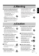
[Safety precaution] Warning If any abnormality occurs. · When there is an abnormal smell or smoke, if you use this unit as it is, this could cause a fire or electric shock, etc. When an abnormality is found, immediately turn off the power switch and pull out the power plug from the power outlet. Check that there is no smoke, etc., then contact your dealer to repair the unit. Do not repair it yourself as it is very dangerous.
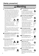
Warning · Do not scratch, damage or process the power cord. Do not bend it forcibly. Also do not put a heavy object on it, do not heat it and do not pull it. If you do, the power cord may be damaged and it may cause a fire, electric shock, etc. × Do not pull the cord. × Do not put a heavy object on it. × Do not damage the cord. × Do not put it near a heating device. · Be careful that this unit is not placed on the power cord. The power cord may be damaged and it may cause a fire, electric shock, etc.
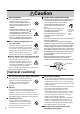
Caution Caution when replacing the lamp. Use of batteries. · Do not use batteries not specified for this unit. Do not use new batteries mixed together with old ones. This may cause a fire, injury due to burst of battery, liquid leakage. · When inserting batteries in this unit, pay attention to the direction of the and polarity indications and insert the batteries correctly. If the polarities are confused, it may cause injury or damage near the unit due to burst batteries, liquid leakage, etc.
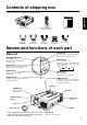
Contents of shipping box Check that the carton contains the following items.
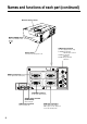
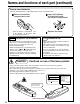
Names and functions of each part (continued) Remote control sensor MAIN POWER switch Main power ON/OFF switch. : OFF : ON VIDEO input terminal (on video-equipped models only) S-VIDEO input terminal Mini DIN 4pin connector VIDEO input terminal RCA Jack AUDIO L/R input terminal RCA Jack AC IN socket Connect the provided power cord.
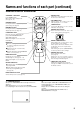
Names and functions of each part (continued) Remote control transmitter MUTE button STANDBY / ON button FREEZE Button Silences the sound. (Cancels the mute when the unit is set in mute mode.) STANDBY/ON Pressing this button partially magnifies a displayed picture. (See page 14) MAGNIFY VOLUME OFF POSITION ON LASER DISK PAD RESET MENU ON RIGHT MOUSE ON 1 When the back light of MENU ON button on, selects or adjusts the menu item. (See page 15) 2 When removes the on-screen menus, works as mouse.
Names and functions of each part (continued) How to insert batteries Insert the provided batteries (LR6 (alkal) into the remote control transmitter. 2 Insert the batteries 1 Remove the battery as illustrated inside the battery compartment. compartment cover. 3 Replace the cover. Slide the battery compartment cover in the direction of the arrow while pressing slightly down on it. Caution Cautions on use of batteries ∑ Do not use batteries not specified for this unit.
Installation Example of the projector and screen installation ENGLISH Determine picture size and projection distance as illustrated below. View from the side View from the top Screen Lens center a Screen (inch) 40 60 80 100 120 150 200 a (inch) Minimum 64 97 130 163 196 244 326 Maximum 84 127 169 213 256 319 a:Distance from the projector to the screen. (tolerance : ±10%) This screen size is full-screen size.
Basic operations To project the picture 2 2 4 STANDBY/ON FREEZE STANDBY/ON 3 MUTE MAGNIFY VOLUME OFF INPUT MUTE LASER POSITION ON MENU 7 RESET 5 RESET MENU ON 7 RIGHT MOUSE ON BLANK TIMER RGB VIDEO INPUT 1 1 Turn the MAIN POWER switch of the projector on.[ I : ON] 2 Press the STANDBY/ON button. 3 4 5 6 Remove the lens cap. 7 · The ON indicator will light up orange. · The ON indicator blinks (green) during warm-up and then lights (green).
Basic operations (continued) To turn off the power 1 STANDBY/ON 1 MUTE ENGLISH FREEZE MAGNIFY VOLUME STANDBY/ON OFF 3 INPUT POSITION ON MUTE LASER MENU RESET RESET RIGHT MENU ON MOUSE ON BLANK TIMER RGB VIDEO INPUT 2 1 Press the STANDBY/ON button, for 1 second. 2 Turn the MAIN POWER switch of the projector off.[ 3 Install the lens cap. · The ON indicator blinks orange and the lamp turns off. (About 1 minute later), the fan stops and the indicator lights up orange.
Basic operations (continued) FREEZE FUNCTION This function can display a still picture (by freezing). This function can be used in combination with a MAGNIFY function. 1 Press the FREEZE button. STANDBY/ON MUTE FREEZE 1, 2 MAGNIFY VOLUME OFF POSITION ON LASER [TO RELEASE FREEZE] 2 Press the FREEZE button. RESET RIGHT MOUSE ON MENU ON Caution Note: When the FREEZE Button is pressed, FREEZE and RELEASE can function alternately.
Adjustments and functions STANDBY/ON MUTE ENGLISH FREEZE STANDBY/ON MAGNIFY VOLUME INPUT OFF MUTE POSITION ON LASER MENU RESET 2, 3 RIGHT RESET 1, 2, 3 1 MENU ON MOUSE ON BLANK TIMER RGB VIDEO INPUT 1 Press the MENU ( OFF button. ) buttons or the MENU ON / · On-screen menus are displayed on the screen. 2 Select the menu to be adjusted using the MENU ( buttons or DISK PAD. ) · Menu displayed in green is selected.
Adjustments and functions (continued) SET UP The menu SET UP serves for the change of parameters influencing the picture and for the move picture position. RGB signal input SETUP INPUT VOLUME BRIGHT CONTRAST V POSIT H POSIT H PHASE H SIZE COLOR BAL IMAGE 123 111 31 1024 R VIDEO signal input OPT. SETUP INPUT IMAGE OPT.
Adjustments and functions (continued) < Auto-adjustment > ENGLISH The projector will automatically adjust four items (V POSIT, H POSIT, H PHASE, H SIZE). When AUTO is selected (the cursor is moved from Manual Operation towards the right) the AUTO Confirm screen shown below will be displayed. < AUTO Confirm Screen > While the AUTO confirmation screen is displayed as illustrated on the upper right, if you shift the cursor upward and select AUTO, the projector will perform auto-adjustment.
Adjustments and functions (continued) IMAGE SETUP INPUT The menu IMAGE serves of the picture inversion. IMAGE OPT. SETUP INPUT IMAGE MIRROR MIRROR BLANK REVEAL MESSAGE SETUP INPUT OPT. SETUP REVEAL OPT. IMAGE BLANK NORMAL H : INVERT V : INVERT H&V : INVERT IMAGE INPUT SETUP INPUT WHITE BLUE BLACK IMAGE MESSAGE FAST OPT. OPT. TURN ON TURN OFF MEDIUM SLOW Adjustment Item MIRROR BLANK REVEAL MESSAGE OPT.
Connection to the video signal terminals 1. Input signal ENGLISH Luminance signal 1.0Vp-p, 75W termination Chrominance signal 0.286Vp-p (burst signal), 75W termination S-VIDEO signal 1.0Vp-p, 75W termination VIDEO signal Input 200mVrms, 20kW below (MAX 3.0Vp-p) Output 0~200mVrms, 1kW AUDIO signal 2. Signal input terminal Chrominance signal Ground Luminance signal Ground S VIDEO input (Mini DIN4 pin) Caution Video input signal terminals have priority in the following order.
Connection to the RGB signal terminal(continued) 3. Example of computer signal Resolution HXV fH (kHz) fV (Hz) 640 X 400 24.8 56.4 640 X 350 37.9 85.1 640 X 400 37.9 720 X 400 Standard Type Note 1 Note 3 Display Dots NEC PC9800 Expanded 1024 X 640 VESA VGA-1 Expanded 1008 X 560 85.1 VESA VGA-2 Expanded 1008 X 640 37.9 85.0 VESA TEXT Expanded 1008 X 640 640 X 480 31.5 59.9 VESA VGA-3 Expanded 1024 X 768 640 X 480 35.0 66.7 Expanded 1024 X 768 640 X 480 37.9 72.
Connection to the RGB signal terminal(continued) 4. Initial set signals Back porch(b) ENGLISH The following signals are initially set. The settings may be different depending on the computer type. In this case, adjust the settings referring to pages 15, 16. Front porch(d) Active(c) DATA HSYNC Sync.(a) Computer/signal VGA-1 (85Hz) VGA-2 (85Hz) PC-9800 TEXT VGA-3 Mac 13" mode VGA-3 (72Hz) VGA-3 (75Hz) VGA-3 (85Hz) SVGA (56Hz) SVGA (60Hz) Horizontal Timing (µs) a b c d 2.0 3.0 20.3 1.0 2.0 3.0 20.3 1.
Connection to the control signal terminal 1. Control signal terminal Pin No. RS-232C Mouse PS/2 ADB Serial 1 2 CLK 3 DATA DATA 1 5 4 10 6 5 6 SELO SELO SELO 7 RTS RTS RTS +5V +5V GND GND RTS 11 15 D-sub 15pin shrink terminal (Male) 8 9 10 GND GND 11 12 13 RDP 14 TDP TD 15 Caution Turn off the power of both the projector and computer before connecting. Connect the computer to the control terminal of the projector using an appropriate cable.
Connection to the control signal terminal (continued) PS/2 mouse 1 CLK 2 DATA 3 4 5 SEL0 6 RTS 7 8 +5V 9 GND 10 11 12 13 14 15 Computer 1 2 3 4 5 6 DATA GND +5V CLK Mini Din 6pin 6 ENGLISH Projector 5 3 4 2 1 PS/2 cable ADB (Mac) mouse Projector DATA RTS +5V GND 1 2 3 4 5 6 7 8 9 10 11 12 13 14 15 Computer 1 2 3 4 ADB (POWER ON) +5V GND Mini Din 4pin 3 4 1 2 ADB cable Serial mouse Projector SEL0 RTS GND TD Caution 1 2 3 4 5 6 7 8 9 10 11 12 13 14 15 Computer 1 2 3 4 5 6 7 8 9 CD
Connection to the control signal terminal (continued) 3. Communication (1) Connect the projector and computer using RS 232C cable. (2) Turn off the computer and after computer is setting up, turn on the projector. (3) Select the data speed (COM.SPEED) and the data format (COM.BITS) of the projector. (See page 18) (4) Start communication.
Connection to the control signal terminal (continued) Control data table Data code MOUSE 00h=stop mouse emulation. 01~7Fh=start mouse emulation COMMUNICATE 0Xh=8N1, 1Xh=7N1 X0h=1200bps, X1h=2400bps, X2h=4800bps, X3h=9600bps, X4h=19200bps POWER 3Eh=Power off (Standby mode), 3Fh=Power on MIRROR 00h=Normal, 01h=H:Invert, 02h=V:Invert, 03h=H&V:Invert INPUT 11h=VIDEO, 21h=RGB1, 22h=RGB2 VIDEO SYSTEM 00h 00h=Auto, 00h 01h=NTSC, 00h 04h=NTSC4.
Connection to the control signal terminal (continued) The procedure of getting the Projector status (1)Computer sends the command '20H'+'yyH' to Projector. (2)Projector reply the command '1xH'+'yyH'+data bytes. The procedure of setting the Projector status (1)Computer sends the command '3xH'+'yyH'+data bytes. (2)Projector changes it’s status. (3)Projector reply the command '1xH'+'yyH'+data bytes which indicate status. Caution · (3) data bytes is not always same as (1) data bytes.
Example of system setup ENGLISH Connecting various equipment. AC Inlet Computer (Note type) S-VIDEO IN 1 RGB IN 2 VIDEO IN CONTROL RGB OUT AUDIO IN L MONO AUDIO IN 1 2 AUDIO OUT R VTR with S-VHS out (video model only) Computer(Desk type) VTR, etc.
Cleaning the air filter Clean the air filter about every 100 hours. 1 Turn the main power switch off and disconnect the power plug from the power outlet. 2 Remove the front filter cover. 3 Clean the air filter using a vacuum cleaner. 4 Attach the air filter on the cover. · When air filter is very dirty, wash it using neutral detergent diluted with water, and dry well. Air filter Caution 28 Filter cover If air filter is strutted with dust, etc., protection circuit will turn the power off.
Lamp Caution ENGLISH Light source lamp has a service life. The picture will become dark or color will be poor when the lamp is used for a long time. If usage of lamp is continued in such cases, it could cause a malfunction. Replace lamp with new one. As reference for replacement time, indicator will operate or message will be displayed when the power is turned on, as shown on page 30~31. In these cases the lamp should be replaced. Consult your dealer.
Lamp (continued) 5 Install the lamp cover and fix it using screws. ∑ To prevent burn, install the lamp cover and secure it using the screws. ∑ Do not turn on the power with lamp cover removed. Lamp cover Whenever the lamp is replaced, reset the total operation time of the lamp. Do not reset if the lamp has not been replaced. Screw 2. Reset the lamp time Pleasecarry out the following operation within 10 minutes from power on, if you replacedthe lamp after 2,000 hours.
Message table (continued) Indicator display ON indicator The ON indicator, LAMP indicator and TEMP indicator will light or blink in the following cases.
Specifications · All specifications are subject to change without notice. Product name Liquid crystal projector Model name CP-X935W/E Display system 3 sheets of liquid crystal panels, 3 primary color lights shutter system 2.3cm (0.9 inchs) Panel size Liquid crystal Drive system TFT active matrix panel Number of pixels 786,432 pixels (V768 X H1024) Lens Zoom lens F=1.7 ~ 2.0 Lamp UHP lamp 120W Speaker 1W+1W (stereo) Power supply AC100 ~ 120V, 2.3A/AC220 ~ 240V, 1.