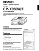
Liquid Crystal Projector Model name CP-X950W/E OPERATING GUIDE Thank you very much for purchasing this Hitachi Liquid Crystal Projector. Please read this operating guide to use correctly. After reading this manual, keep it carefully for future reference. O N TE LA M P M M IN P ZO U PU T AN STN /O TE O M S CU FO U EN M T SE RE D BY Outline This Liquid Crystal Projector can display various computer signals and NTSC/PAL/SECAM video signals.
FOR THE CUSTOMERS IN U.K THIS PRODUCT IS SUPPLIED WITH A TWO PIN MAINS PLUG FOR USE IN MAINLAND EUROPE. FOR THE U.K PLEASE REFER TO THE NOTES ON THIS PAGE. IMPORTANT FOR UNITED KINGDOM WORDING FOR CLASS I EQUIPMENT INSTRUCTION BOOKS AND LABELS The mains lead on this equipment is supplied with a moulded plug incorporating a fuse, the value of which is indicated on the pin face of the plug. Shoud the fuse need to be replaced, an ASTA or BSI approved BS 1362 fuse must be used of the same rating.
WARNING: This equipment has been tested and found to comply with the limits for a Class A digital device, pursuant to Part 15 of the FCC Rules. These limits are designed to provide reasonable protection against harmful interference when the equipment is operated in a commercial environment.
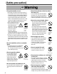
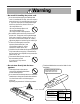
[Safety precaution] Warning Λ If any abnormality occurs. there is an abnormal smell or smoke, if •When you use this unit as it is, this could cause a fire or electric shock, etc. When an abnormality is found, immediately turn off the power switch and pull out the power plug from the power outlet. Check that there is no smoke, etc., then contact your dealer to repair the unit. Do not repair it yourself as it is very dangerous.
Warning Λ Be careful in handling the power cord. not scratch, damage or process the power •Do cord. Do not bend it forcibly. Also do not put a heavy object on it, do not heat it and do not pull it. If you do, the power cord may be damaged and it may cause a fire, electric shock, etc. •Do not pull the cord. •Do not put a heavy object on it. •Do not damage the cord. •Do not put it near a heating device. Be careful that this unit is not placed on the power cord.
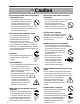
Caution Λ Do not step on this unit or do not put a heavy object on it. not step on this unit. Especially •Do pay attention if children are present. If you do, the unit may fall over or may be broken causing an injury. Do not put a heavy object on this unit. If you do, the unit may fall due to its imbalance or it may drop, causing an injury. • Λ Do not block the ventilation holes. Do not block the ventilation holes.
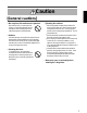
Caution [General cautions] Λ Do not place this unit where it gets hot. Be careful since if you place the unit outdoors, in a place exposed to direct sunlight or near a heating device, the cabinet and parts could be affected. Λ Volume. Use at the proper volume level so that it does not bother persons in the neighborhood. Especially, since the sound is likely to carry well at the night even at a low volume, consider the neighborhood to a good living environment. Λ Cleaning the lens.
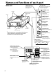
Names and functions of each part Main unit LAMP indicator ON indicator This lights when the lamp does not light. (See page 29) This blinks in the standby mode and lights in the operation mode. (See page 29) O STANDBY / ON button N Speaker Y DB AN ST N /O P P M TE M LA Remote control sensor Handle Power ON/OFF button. OFF sets the unit in standby mode.
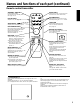
Names and functions of each part (continued) Remote control transmitter STANDBY / ON button MUTE button Power ON/OFF button. OFF sets the unit in standby mode. (See page 12, 13) Silences the sound. (Cancels the mute when the unit is set in mute mode.) STANDBY/ON MUTE VOLUME button FOCUS button Adjusts volume. The sound is loud or low while pressing the “+” or “–” button. Adjusts focus. (See page 12) FOCUS ZOOM VOLUME LASER ON ZOOM button Laser pointer ON/OFF button.
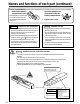
Names and functions of each part (continued) How to insert batteries insert the provided batteries (LR6 (alkali)) into the remote control transmitter. ¡ Remove the battery ™ Insert the batteries as compartment cover. illustrated inside the battery compartment. Slide the battery compartment cover in the direction of the arrow while pressing slightly down on it. £ Replace the cover. Caution Cautions on use of batteries Do not use batteries not specified for this unit.
Installation Example of the projector and screen installation Determine picture size and projection distance as illustrated below. View from the top View from the side Screen Lens center b a a (inch) Screen (inch) b (inch) Minimum Maximum 40 60 89 3.4 60 89 134 5.1 80 119 179 6.9 100 149 224 8.6 120 179 269 10.3 150 224 336 12.9 200 298 448 17.2 a: Distance from the projector to the screen. (±10%) b: Length from the center of the lens to the bottom of the picture.
Basic operations To project the picture 7 2 2 4 O N 5 4 STANDBY/ON FOCUS MUTE ZOOM VOLUME TE LA M P M M IN P ZO U PU T AN STN /O TE O M S CU FO U EN M T SE RE D BY POSITION ON LASER 5 RESET MENU ON 1 7 RIGHT MOUSE ON BLANK TIMER RGB 1/2 VIDEO 1/2 INPUT 3 1 Turn the MAIN POWER switch of the projector on. [ I : ON] •The ON indicator will light up orange. 2 Press the STANDBY/ON button. •The ON indicator blinks (green) and then lights (green).
Basic operations (continued) To turn off the power 1 1 STANDBY/ON MUTE O N TE LA M P M M IN P ZO U PU T AN STN /O FOCUS ZOOM VOLUME TE O M S CU FO U EN M T SE RE D BY POSITION ON LASER RESET 2 RIGHT MENU ON MOUSE ON BLANK TIMER RGB 1/2 3 1 VIDEO 1/2 INPUT Press the STANDBY/ON button, for 1 second. •The ON indicator lights up orange and the lamp turns off. (About 1 minute later), the fan stops and the indicator blinks orange.
Adjustments and functions STANDBY/ON 1, 2 FOCUS ZOOM POSITION ON 1 U EN M VOLUME LASER 2 T SE RE RESET MENU ON 1 MUTE Press the MENU ( button. RIGHT 1 MOUSE ON BLANK TIMER RGB 1/2 VIDEO 1/2 ) buttons or the MENU ON / OFF •On-screen menus are displayed on the screen. 2 Select the menu to be adjusted using the MENU ( buttons or DISK PAD. ) •Menu displayed in green is selected. 3 Select the item to be adjusted using the MENU ( buttons or DISK PAD.
Adjustments and functions (continued) SET UP The menu SET UP serves for the change of parameters influencing the picture and for the move picture position. RGB signal input SETUP INPUT VOLUME BRIGHT CONTRAST V POSIT H POSIT H PHASE H SIZE COLOR BAL IMAGE VIDEO signal input SETUP OPT. VOLUME BRIGHT CONTRAST SHARPNESS COLOR TINT COLOR BAL 121 57 7 800 R INPUT IMAGE R OPT.
Adjustments and functions (continued) INPUT The menu INPUT serves for the selection of input source. SETUP INPUT IMAGE OPT. SETUP RGB1 RGB2 VIDEO1 VIDEO2 TEST PATTERN INPUT IMAGE SYSTEM AUTO NTSC PAL SECAM NTSC4.43 M-PAL RGB1 RGB2 VIDEO1 VIDEO2 TEST PATTERN Adjustment Item Details of adjustment RGB1 Selects the RGB 1 terminal. RGB2 Selects the RGB 2 terminal. VIDEO1 Selects the VIDEO 1 terminal. OPT. VIDEO2 Selects the VIDEO 2 terminal. TEST PATTERN Selects the TEST PATTERN.
Adjustments and functions (continued) SETUP INPUT IMAGE MESSAGE OPT. TURN ON TURN OFF Adjustment Item Details of adjustment Inverts the picture horizontally or vertically. NORMAL Not invert. H : INVERT Inverts the picture horizontally. V : INTERT Inverts the picture vertically. H&V : INVERT Inverts the picture horizontally and vertically. MIRROR BLANK Selects the blank color of signal or pressing BLANK ON button. REVEAL Selects the speed of revelation. See page 9 “BLANK ON button”.
Adjustments and functions (continued) SETUP INPUT SETUP IMAGE OPT. COM. SPEED (bps) 1200 2400 4800 9600 19200 INPUT OPT. IMAGE SETUP INPUT SETUP INPUT SETUP INPUT 10 min. IMAGE AUTO OFF OPT. SETUP START UP 0 min. STOP Adjustment Item INPUT IMAGE IMAGE Details of adjustment Selects the data format of transmission. Sets the minutes of timer. (0 ~ 99) Selects the language on-screen menu.
Connection to the video signal terminals 1. Input signal S-VIDEO signal Luminance signal Chrominance signal 1.0Vp-p, 75 Ω termination VIDEO signal AUDIO signal 1.0Vp-p, 75 Ω termination 0.286Vp-p (burst signal), 75 Ω termination Input 200mVrms, 20 kΩ below (MAX 3.0Vp-p) Output 0~200mVrms, 1k Ω 2. Signal input terminal Chrominance signal Ground Luminance signal Ground S VIDEO input (Mini DIN4 pin) Caution Video input signal terminals have priority in the following order.
Connection to the RGB signal terminal (continued) 3. Example of computer signal Resolution H ×V fH (kHz) fV (Hz) 640 × 350 31.5 70.1 640 × 400 24.8 640 × 400 Standard Type Note 3 Display Dots H×V VGA-1 Expanded 1024 × 560 56.4 NEC PC9800 Expanded 1024 × 640 31.5 70.1 VGA-2 Expanded 1024 × 640 640 × 480 43.3 85.0 VESA Expanded 853 × 640 640 × 480 31.5 59.9 VESA Expanded 1024 × 768 640 × 480 35.0 66.7 Expanded 1024 × 768 640 × 480 37.9 72.
Connection to the RGB signal terminal (continued) 4. Initial set signals The following signals are initially set. The settings may be different depending on the computer type. In this case, adjust the settings referring to pages 14, 15. Back porch (b) Front porch (d) Active (c) DATA HSYNC Sync. (a) Horizontal Timing (µs) Computer/Signal a b c Horizontal Timing (µs) Computer/Signal d a b c d 0.3 VGA-1 3.8 1.9 25.4 0.6 SVGA (75Hz) 1.6 3.3 16.3 PC9800 3.0 3.8 30.4 3.0 SVGA (85Hz) 1.
Connection to the control signal terminal 1. Control signal terminal . Pin No Mouse RS232C PS/2 ADB 2 CLK DATA 3 DATA Serial RS232C (option CP-X950E) Serial mouse (option CP-X950W) 1 4 5 6 SELO SEL0 7 RTS RTS SEL0 RTS RTS D-sub 15pin shrink terminal (Male) 8 9 10 GND +5V +5V GND GND GND 11 12 13 RDP 14 TDP TD 15 Caution Turn off the power of both the projector and computer before connecting.
Connection to the control signal terminal (continued) PS/2 mouse Projector 1 CLK 2 DATA 3 4 5 SEL0 6 RTS 7 8 +5V 9 GND 10 11 12 13 14 15 ADB (Mac) mouse Serial mouse (option CP-X950W) Projector 1 2 DATA 3 4 5 6 RTS 7 8 +5V 9 GND 10 11 12 13 14 15 Projector 1 2 3 4 5 SELO 6 RTS 7 8 9 GND 10 11 12 13 TD 14 15 Computer 1 2 3 4 5 6 DATA Mini Din 6pin GND +5V CLK 6 5 4 3 1 2 PS/2 cable Computer 1 2 3 4 ADB (POWER ON) +5V GND Mini Din 4pin 4 3 1 2 ADB cable Computer 1 2 3 4 5 6 7 8 9 C
Connection to the control signal terminal (continued) 3. Communication (1) (2) (3) (4) Connect the projector and computer using RS 232C cable. Turn on the computer and after computer is setting up, turn on the projector. Select the data speed (COM.SPEED) and the data format (COM.BITS) of the projector. (See page 18) Start communication.
Connection to the control signal terminal (continued) Control data table Item Data code MOUSE 00h=stop mouse emulation.
Connection to the control signal terminal (continued) The procedure of getting the Projector status. (1) Computer sends the command ’20H’ + ‘yyH’ to Projector. (2) Projector reply the command ‘1xH’ + ‘yyH’ + data bytes. The procedure of setting the Projector status (1) Computer sends the command ‘3xH’ + ‘yyH’ + data bytes. (2) Projector changes it’s status. (3) Projector reply the command ‘1xH’ + ‘yyH’ + data bytes which indicate status. Caution (3) data bytes is not always same as (1) data bytes.
Example of system setup Connecting various equipment. AC Inlet VCR with S-VHS out (video model only) Computer (Note type) Computer (Desk type) Audio amplifying equipment VCR, etc. (video model only) CRT Display Caution Turn power off to all devices before connecting. Refer to the instruction manual of each device before connecting. Cleaning the air filter Clean the air filter about every 100 hours or when “CHECK THE AIR FLOW” is displayed.
Cleaning the air filter (continued) 3 Clean the air filter using a vacuum cleaner. If dirt is still present, wipe the air filter with a cloth moistened with water or neutral detergent and wipe with a dry cloth. 4 Re-install the air filter. Caution • If air filter is stutted with dust, etc., protection circuit will turn the power off. • “CHECK THE AIR FLOW” is displayed when you block the ventilation holes. Lamp The following symptoms may indicate a worn lamp : • A dark picture.
Indicator display The ON indicator, LAMP indicator and TEMP indicator will light or blink in the following cases. Indicator status ON indicator Meaning Remedy Lights orange Standby mode ————————————— Blinks green During warming up ————————————— Lights green During operation ————————————— Blinks orange During cooling down ————————————— Lights red Under the mode Under the method Lamp cannot light Cool projector by power off for 20 minutes.
Specifications • All specifications are subject to change without notice. Product name Liquid crystal projector Model Name CP-X950W/E Display system 3 sheets of liquid crystal panels, 3 primary color lights shutter system Liquid crystal panel Panel size 3.3 cm (1.3 inches) Drive system TFT active matrix Number of pixels 786.432 pixels (V768 × H1,024) Lens Zoom lens F=2.3 ∼ 3.0 Lamp Metal halide lamp 260W Speaker 2W + 2W (stereo) Power supply AC100 ∼ 120V, 5A / AC220 ∼ 240V, 2.