Please read this user's manual thoroughly to ensure correct usage through understanding. BEDIENUNGSANLEITUNG Bitte lessen Sie diese Bedienungsanleitung zugunsten der korrekten Bedienung aufmerksam. MANUEL D'UTILISATION Nous vous recommandons de lire attentivement ce manuel pour bien assimiler le fonctionnement de l'appareil.
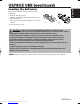
Liquid Crystal Projector ENGLISH USER'S MANUAL Thank you for purchasing this liquid crystal projector. WARNING • Please read the accompanying manual “SAFETY INSTRUCTIONS” and this “USER'S MANUAL” thoroughly to ensure correct usage through understanding. After reading, store this instruction manual in a safe place for future reference. NOTE • The information in this manual is subject to change without notice.
FEATURES This liquid crystal projector is used to project various computer signals as well as NTSC / PAL / SECAM video signals onto a screen. Little space is required for installation and large images can easily be realized. Outstanding Brightness The UHB lamp and high-efficiency optical system assure a high level of brightness. Partial Magnification Function Interesting parts of images can be magnified for closer viewing. Distortion Correction Function Distortion-free images are quickly available.
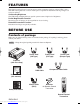
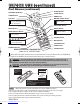
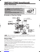
BEFORE USE (continued) ZOOM Button ENGLISH Part Names FOCUS Button ZOOM KEYSTONE Button FOCUS KEYSTONE INPUT Button INPUT MENU STANDBY/ON Button STANDBY/ON LAMP POWER TEMP MENU Button RESET LAMP Indicator RESET Button POWER Indicator TEMP Indicator Control Panel (Refer to P.
BEFORE USE (continued) Part Names (continued) STANDBY/ON Button BLA VIDEO Button N DBY/O STAN Disk Pad E LAS BLANK Button LASER Button NK R RGB Button B RG MOUSE / RIGHT Button O VIDE Used to operate the mouse shift function and left click function. Used to click the right mouse button. KEYSTONE Button AUTO Button MENU Button O AUT MENU SELECT Button ME Used to click the left mouse button.
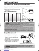
BEFORE USE (continued) Install the AA batteries into the remote control transmitter. 1. Remove the battery cover. Push the knob while lifting up the battery cover. 2. Load the batteries. Make sure the plus and minus poles are correctly oriented. 3. Close the battery cover. ENGLISH Loading the Batteries 1 2 CAUTION • Use only the specified batteries with this remote control transmitter. Also, do not mix new and old batteries.
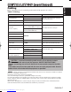
INSTALLATION Installation of the Projector and Screen Refer to the drawing and table below for determining the screen size and projection distance. The projection distances shown in the table below Screen are for full size (1024 x 768 dots). a: Distance from the projector to the screen. (±10%) b: Distance from the lens center to the bottom of the screen. (±10%) Table 1. Installation Reference Screen size [inches (m)] a [inches (m)] Min. Max. b [inches (cm)] 40 (1.0) 60 (1.5) 55 (1.4) 85 (2.2) 73 (1.
INSTALLATION (continued) ENGLISH Cabling Refer to the table below for connecting each terminal of the projector to a device. Table 2.
INSTALLATION (continued) Power Connection Use the correct power cord depending on the power outlet to be used. Connect the AC inlet of the projector to the power outlet firmly by the power cord. CAUTION • Be carful in handling the power cord according to instructions of the accompanying manual "SAFETY INSTRUCTIONS" and this manual. • Connect the power cord firmly. Avoid using a loose, unsound outlet or failed contact.
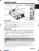
POWER Indicator STANDBY/ON Button STANDBY/ ON Button BLANK STANDBY/ON LASER VIDEO RGB ZOOM button FOCUS button AUTO MENU KEYSTONE MENU SELECT RESET POSITION Power Switch FREEZE MAGNIFY PinP MUTE OFF FOCUS button FOCUS Lens cap ZOOM VOLUME ZOOM button Power ON 1. Check that the power cord is connected correctly. 2. Set the power switch to [ | ]. The standby mode is selected, and the POWER indicator is turned to orange. 3.
OPERATIONS (continued) Basic Operation The basic operations shown in Table 3 is performed from the supplied remote control transmitter or the projector control panel. Items indicated by (*) may be used from the control panel. Table 3 . Basic Operation Item Description Select Input Signal (*) : Press the INPUT button. RGB IN 1 → RGB IN 2 → DVI → VIDEO → S-VIDEO → COMPONENT VIDEO (→ RGB IN 1) Select RGB Input : Press the RGB button.
OPERATIONS (continued) ENGLISH Items indicated by (*) may be used from the control panel. Table 3. Basic Operation (continued) Item Description VOLUME Volume Adjustment : Press the VOLUME MUTE Set/Clear Mute Mode : Press the MUTE button. No sound is heard in the MUTE mode. AUTO Automatic Adjustment at RGB Input : Press the AUTO button. Horizontal position(H.POSIT), vertical position (V.POSIT),clock phase (H.PHASE), and horizontal size(H.SIZE) are automatically adjusted.
OPERATIONS (continued) Setup Menu SETUP The following adjustments and settings are possible when SETUP is selected at the top of the menu. Part of the Setup menu differs between RGB input and video input. Select an item with the and buttons, and start operation. Use the Single menu to reduce menu size (see Table 3, MENU SELECT). Table 4. Setup Menu Item INPUT BRIGHT CONTRAST V POSIT H POSIT H PHASE H SIZE COLOR BAL R COLOR BAL B ASPECT IMAGE SETUP OPT. 0 -2 INPUT IMAGE OPT.
Input Menu The following functions are available when INPUT is selected on the menu. Select an item with the and buttons, and start or stop operation with the and buttons. The function indicated (**) are effective on video input mode only, not on RGB input mode, except in the P.IN P. window on RGB input mode. Table 5. Input Menu Item AUTO RGB SETUP INPUT AUTO RGB VIDEO VIDEO NR Progressive BLACK HDTV IMAGE OPT.
OPERATIONS (continued) Image Menu SETUP The following adjustments and settings are available when IMAGE is selected on the menu. Select an item with the and buttons, and start or stop operation with the and buttons. Table 6. Image Menu Item INPUT BLANK START UP MyScreen MIRROR P.IN P. POSIT P.IN P. INPUT GAMMA IMAGE OPT. MyScreen ORIGINAL Description BLANK Select Blank Screen: Select the screen in case of the BLANK mode with the / button.
Options Menu SETUP The following adjustments and settings are available when OPT. is selected on the menu. Select an item with the and buttons, and start operation. INPUT IMAGE OPT. 16 VOLUME MENU COLOR LANGUAGE AUTO OFF SYNC ON G WHISPER Table 7. Options Menu Item Description ↔ Increase VOLUME VOLUME Volume Adjustment: Reduce VOLUME MENU COLOR Select Menu Background Color: Select with the and buttons. LANGUAGE Operation Start/Stop: Press the / button.
OPERATIONS (continued) No Signal Menu The same adjustments and settings are available with the Image and Options menus when the MENU button is pressed during display of the “NO INPUT IS DETECTED ON ***” or “SYNC IS OUT OF RANGE ON ***” message while no signal is received. VOLUME BLANK START UP MIRROR MENU COLOR LANGUAGE AUTO OFF SYNC ON G WHISPER 16 Table 8.
Lamp HIGH VOLTAGE HIGH TEMPERATURE HIGH PRESSURE Contact your dealer before replacing the lamp. For the optional lamp, see the item “Option Parts” of the Table 12. Before replacing the lamp, switch power OFF, remove the power cord from the power outlet, and wait approximately 45 minutes until the lamp has cooled. The lamp may explode if handled at high temperatures. WARNING A mercury lamp used in this LCD projector is made of glass and has high internal pressure.
MAINTENANCE (continued) Replacing the Lamp 1. Switch the projector OFF, remove the power cord from the power outlet, and wait at least 45 minutes for the unit to cool. 2. Prepare a new lamp. 3. Check that the projector has cooled sufficiently, and gently turn it upside down. 4. Loosen the screw as shown in the diagram, and remove the lamp cover. 5. Loosen the two screws, and gently remove the lamp while holding the grips. Touching the inside of the lamp case may result in uneven coloring. 6.
Air Filters filter cover Cleaning Air Filters This projector uses 2 air filters. These air filters should be cleaned as described below at intervals of approximately 100 hours. 1. Switch the projector power supply OFF, and remove the power cord from the power outlet. 2. Remove the filter cover and the air filter. 3. Clean the air filter with a vacuum cleaner. 4. Set the air filter and the filter cover.
TROUBLESHOOTING OSD Message The messages as described below may appear on the screen at power ON. Take the appropriate measures when such messages appears. Table 9. OSD Message Message CHANGE THE LAMP AFTER REPLACING LAMP, RESET THE LAMP TIME. (*1) Contents The usage time of lamp will be reaching 2000 hr shortly.(*2) It is recommended to replace the lamp soon. Prepare a new lamp as a replacement. The usage time of lamp will be reaching 2000 hr shortly.
Indicators Message The POWER indicator, LAMP indicator, and TEMP indicator are lit and blank as follows. Take the appropriate measures. Table 10. Indicators Message POWER LAMP TEMP indicator indicator indicator Contents Lights orange Turns off Turns off The Standby mode has been set. Blinks green Turns off Turns off Warming up. Please wait. Lights green Turns off Turns off ON. Normal operation possible. Blinks orange Turns off Turns off Cooling. Please wait.
TROUBLESHOOTING (continued) Symptom Before requesting repair, check in accordance with the following chart. If the situation cannot be corrected, then contact your dealer. Table 11. Symptom Symptom The power is not turned on. Possible cause Remedy The main power switch is not turned on. Turn on the main power switch. The power cord is disconnected. Plug the power cord into an AC power outlet. The main power was disconnected during operation by the power failure and so on.
Table 12. Specifications Item Product name Liquid crystal panel Specification Liquid crystal projector Panel size 3.3 cm (1.3 type) Drive system TFT active matrix Pixels 786,432 pixels (1024 horizontal x 768 vertical) Lens Zoom lens F=1.7 ~ 2.3 f=49.0 ~ 64.0 mm Lamp 275 W UHB Speaker 1.2 W + 1.2W (Stereo) Power supply AC100 ~ 120V, 4.7A / AC220 ~ 240V, 2.0A Power consumption 440W Temperature range 0 ~ 35°C (Operating) Size 289 (W) x 144 (H) x 350 (D) mm Weight (mass) 6.
WARRANTY AND AFTER-SERVICE If a problem occurs with the equipment, first refer to the P.20 “TROUBLESHOOTING” section and run through the suggested checks. If this does not resolve the problem contact your dealer or service company. They will tell you what warranty condition is applied. ENGLISH-24 Downloaded from www.Manualslib.
TECHNICAL 350 395 Dimension Diagram 289 144 88 139 308.5 Unit : mm 30.5 Signal Connector Pin Assignment 1. D-sub 15-pin Shrink Connector (RGB IN 1/RGB IN 2/RGB OUT) Pin No 1 2 3 4 5 6 7 8 Signal Video input Red Video input Green Video input Blue Ground Ground Red Ground Green Ground Blue Pin No 9 10 11 12 13 14 Signal Pin No Ground 15 RGB IN 1: SDA(DDC) RGB IN 2: RGB OUT: H. sync./ Composite sync.
TECHNICAL (continued) Example of computer signal Resolution H×V fH (kHz) fV (Hz) Rating Signal mode Display mode 720 × 400 37.9 85.0 VESA TEXT Zoom in 640 × 480 31.5 59.9 VESA VGA (60Hz) Zoom in 640 × 480 35.0 66.7 Mac13"mode Zoom in 640 × 480 37.9 72.8 VESA VGA (72Hz) Zoom in 640 × 480 37.5 75.0 VESA VGA (75Hz) Zoom in 640 × 480 43.3 85.0 VESA VGA (85Hz) Zoom in 800 × 600 35.2 56.3 VESA SVGA (56Hz) Zoom in 800 × 600 37.9 60.
TECHNICAL (continued) Initial set signals The following signals are used for the initial settings. The signal timing of some computer models may be different. In such case, refer to adjust the V.POSIT and H.POSIT of the menu. Back porch b Front porch d Display interval c Back porch b Front porch d Display interval c DATA DATA HSYNC VSYNC Sync a Computer / Signal Sync a Horizontal signal timing (µs) TEXT a 2.0 b 3.0 c 20.3 d 1.0 VGA (60Hz) 3.8 1.9 25.4 Mac 13"mode 2.1 3.2 VGA (72Hz) 1.
TECHNICAL (continued) Connection to the Mouse Control 1. PS/2, ADB or Serial Mouse (1) Turn off the projector and computer, and connect the two units with the appropriate cable. For PS/2 mouse control (for IBM and compatible), use the enclosed mouse cable. For others, consult your dealer. (2) Disconnect the USB cable from the projector if it is connected. Then turn on the projector. (3) Turn on the computer. (4) Start the mouse function.
TECHNICAL (continued) ADB Mouse Projector CONTROL Terminal DATA D-sub 15-pin shrink jack 6 2 3 4 5 7 8 9 10 11 12 13 14 15 1 RTS +5V GND 1 2 3 4 5 6 7 8 9 10 11 12 13 14 15 Computer 1 ADB 2 (POWER ON) 3 +5V 4 GND Mouse jack Mini DIN 4-pin 3 4 1 2 Serial Mouse CONTROL Terminal D-sub 15-pin shrink jack 6 2 3 4 5 7 8 9 10 11 12 13 14 15 1 Projector 1 2 3 4 5 SEL0 6 RTS 7 8 9 GND 10 11 12 13 TD 14 15 1 2 3 4 5 6 7 8 9 Computer CD RD TD DTR GND DSR RTS CTS RI Mouse jack D-sub 9-pin 1 2 6 3 7
TECHNICAL (continued) RS-232C communication (1) Turn off the projector and computer power supplies and connect with the RS-232C cable. (2) Turn on the computer power supply and, after the computer has started up, turn on the projector power supply.
TECHNICAL (continued) Requesting projector status (Get command) (1) Send the request code Header + Command data (‘02H’+‘00H’+ type (2 bytes) +‘00H’+‘00H’) from the computer to the projector. (2) The projector returns the response code ‘1DH’+ data (2 bytes) to the computer. Changing the projector settings (Set command) (1) Send the setting code Header + Command data (‘01H’+‘00H’+ type (2 bytes) + setting code (2 bytes)) from the computer to the projector.
TECHNICAL (continued) Command data chart Names Blank Color Operation type Set Mirror Freeze Set Language Set Set Setting code 06 00 3B D3 01 00 00 30 00 00 Orange BE EF 03 06 00 AB D2 01 00 00 30 01 00 Green BE EF 03 06 00 5B D2 01 00 00 30 02 00 Blue BE EF 03 06 00 CB D3 01 00 00 30 03 00 Purple BE EF 03 06 00 FB D1 01 00 00 30 04 00 White BE EF 03 06 00 6B D0 01 00 00 30 05 00 Black BE EF 03 06 00 9B D0 01 00 00 30 06 00 MyScreen BE EF 03
TECHNICAL (continued) Command data chart Operation type Command data Header CRC Action Type Setting code Get BE EF 03 06 00 7C D2 02 00 07 30 00 00 Increment BE EF 03 06 00 1A D2 04 00 07 30 00 00 Decrement BE EF 03 06 00 CB D3 05 00 07 30 00 00 Get BE EF 03 06 00 08 86 02 00 10 31 00 00 Increment BE EF 03 06 00 6E 86 04 00 10 31 00 00 Decrement BE EF 03 06 00 BF 87 05 00 10 31 00 00 Brightness Reset Execute BE EF 03 06 00 58 D3 06 00 00 70 00 0
TECHNICAL (continued) Command data chart Names Mute Operation type Set Brightness Contrast Color Balance R Color Balance B Keystone_V Keystone_H Aspect V.Position H.Position H.Size H.
TECHNICAL (continued) Command data chart Names Operation type Sharpness Color Tint Set Video Format Video NR Action Type Setting code BE EF 03 06 00 F1 72 02 00 01 22 00 00 Increment BE EF 03 06 00 97 72 04 00 01 22 00 00 Decrement BE EF 03 06 00 46 73 05 00 01 22 00 00 Get BE EF 03 06 00 B5 72 02 00 02 22 00 00 Increment BE EF 03 06 00 D3 72 04 00 02 22 00 00 Decrement BE EF 03 06 00 02 73 05 00 02 22 00 00 Get BE EF 03 06 00 49 73 02 00 03 22
TECHNICAL (continued) Command data chart Names Operation type 03 06 00 02 23 01 00 01 23 00 00 03 06 00 92 22 01 00 01 23 01 00 bottom left BE EF 03 06 00 62 22 01 00 01 23 03 00 bottom right BE EF 03 06 00 F2 23 01 00 01 23 02 00 BE EF 03 06 00 31 23 02 00 01 23 00 00 RGB BE EF 03 06 00 BA 22 01 00 03 23 00 00 Video BE EF 03 06 00 2A 23 01 00 03 23 01 00 BE EF 03 06 00 89 22 02 00 03 23 00 00 Video BE EF 03 06 00 D6 22 01 00 02 23 01 00 S-
REGULATORY NOTICES FCC Statement Warning WARNING: This equipment has been tested and found to comply with the limits for a Class B digital device, pursuant to Part 15 of the FCC Rules. These limits are designed to provide reasonable protection against harmful interference in a residential installation. This equipment generates, uses, and can radiate radio frequency energy and, if not installed and used in accordance with the instructions, may cause harmful interference to radio communications.
Hitachi America, Ltd. Hitachi France Computer Division 2000 Sierra Point Parkway, MS760 Brisbane, CA 94005-1835 Tel: +1-800-225-1741 Fax: +1-650-244-7776 www.hitachi.com/lcd. Immeuble, 'Ariane', 18 Rue Grange Dame Rose, B.P. 134, 78148 Velizy, Cedex, France Tel: +33-1-34630542 Fax: +33-1-34650761 Hitachi Canada, Ltd.