MODEL D 10YB POWER TOOLS D ANGLE DRILL D 10YB LIST No. 0193 TECHNICAL DATA AND SERVICE MANUAL Jun.
Notice for use Specifications and parts are subject to change for improvement. Refer to Hitachi Power Tool Technical News for further information. CONTENTS Page 1. PRODUCT NAME •••••••••••••••••••••••••••••••••••••••••••••••••••••••••••••••••••••••••••••••••••••••••••••••••••••••••••••••••••••• 2. MARKETING OBJECTIVE 3.
1. PRODUCT NAME Hitachi Angle Drill, Model D 10YB 2. MARKETING OBJECTIVE The Model D 10YB has been developed based on the current Model D 10YA (10 mm) to meet the market demand for an angle drill with a forward/reverse changeover switch, a small-diameter housing, and a small head. The key features of the Model D 10YB are as follows.
-1. Selling Point Descriptions 4-1-1. Easy-to-grip small-diameter housing As in the case of disc grinders, a small-diameter housing makes it easy to grip and improves operability. The slide switch located on the lower portion of the housing can be operated while gripping the tool. 4-1-2. Forward/reverse changeover switch The Model D 10YB is equipped with a forward/reverse changeover switch. This switch expands the application range to such tasks as loosening screws and locked drill bits. 4-1-3.
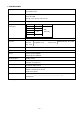
. SPECIFICATIONS Capacity Steel: 10 mm (3/8") Wood: 22 mm (7/8") Drill chuck Mount type: 3/8"-24UNF Chuck: 10 TLRD Capacity: 1.5 to 10 mm (1/16" to 3/8") Power source AC single phase 50/60 Hz Voltage, current and Voltage (V) Current (A) Power input (W) power input 110 115 220 230 240 4.8 4.6 2.3 500 (0.67 HP) 2.
. COMPARISONS WITH SIMILAR PRODUCTS 6-1. Specification Comparisons Hitachi Model Structural features Characteristics Catalog specifications Item D 10YB D 10YA B C Steel mm 10 (3/8") 10 (3/8") 10 (3/8") 10 (3/8") Wood mm 22 (7/8") 15 (5/8") 22 (7/8") 15 (5/8") mm 10 (3/8") 10 (3/8") 10 (3/8") 10 (3/8") W 500* (0.67HP) 400 (0.54HP) 400 (0.54HP) 300 (0.40HP) /min. 500 to 2,300 300 to 2,300 0 to 1,100 0 to 1,400 kg 1.5 (3.3 lbs.) 1.7 (3.8 lbs.) 1.6 (3.5 lbs.) 1.6 (3.
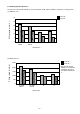
6-2. Drilling Speed Comparisons The figures below show the drilling speed of the Model D 10YB compared with the competitors' existing models. (1) Drilling in steel 6.5 mm dia. 10 mm dia. Drilling speed (mm/min.) 30 25 20 15 10 5 0 D 10YB Hitachi D 10YA Hitachi C B Model name (2) Drilling in wood 15 mm dia. 22 mm dia. * Drilling speed (mm/min.) 2,500 * Note that 22 mm dia. drilling is more than the maximum capacity of the Model D 10YA and C.
7. PRECAUTIONS IN SALES PROMOTION In the interest of promoting the safest and most efficient use of the Model D 10YB Angle Drill by all of our customers, it is very important that at the time of sale the salesperson carefully ensures that the buyer seriously recognizes the importance of the contents of the Handling Instructions, and fully understands the meaning of the precautions listed on the Name Plate attached to each tool. 7-1.
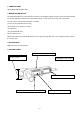
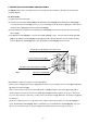
8. PRECAUTIONS IN DISASSEMBLY AND REASSEMBLY The [Bold] numbers in the descriptions below correspond to the item numbers in the parts list and exploded assembly diagram. 8.1 Disassembly (1) Replacement of the drill chuck (a) Insert the Chuck Handle 10TLRD [26] into the Drill Chuck 10TLRD [25] until the Drill Chuck 10TLRD [25] is secured to the Chuck Cover [21] (See Fig. 1). To avoid damage to the Chuck Cover [21], put a cloth between the Chuck Cover [21] and the Chuck Handle 10TLRD [26].
Gear Cover [2] Hex. bar wrench Drill Chuck 10TLRD [25] Gear [20] Secure two pins of the J-309 tool into the holes at the rear of the gear. Tap on these two holes from the bottom. Pin (J-309) J-309 tool Secured to the vise. Fig. 3 Fig. 2 (2) Disassembly of the spindle section (a) Remove the four Seal Lock Hex. Socket Hd. Botls M3 x 12 [22] and remove the Chuck Cover [21]. (b) Remove the four Tapping Screws D5 x 40 [1] from the Gear Cover [2] and remove the Gear Cover [2] from the Inner Cover [8].
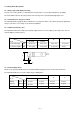
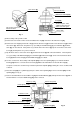
(3) Disassembly of the second pinion (a) Place the end surface of the First Gear [5] on a cylindrical jig and press down on the Second Pinion [4] with a hand press. Then the Second Pinion [4] can be removed (See Fig. 6). Press down Press down Second Pinion [4] Spindle [19] First Gear [5] Gear [20] Cylindrical jig Cylindrical jig 15 mm dia. 18 mm dia. Fig. 5 Fig.
(h) Remove the Switch [46] by slightly pushing the two protrusions of the Controller Circuit Holder [34]. Be careful not to apply excessive force to the protrusions to prevent damages to the protrusions. ( i ) Loosen the two Tapping Screws (W/Flange) D4 x 20 [37] and remove the Controller Circuit Holder [34] from the Housing Ass'y [32].
8.2.2 Reassembly of the power source section (1) Before inserting the Stator Ass'y [13] into the Housing Ass'y [32], be sure to mount the Slide Bar [45]. (2) Insert the Stator Ass'y [13] into the Housing Ass'y [32] in the direction shown in Fig. 9, paying attention to the direction of the internal wires of the Stator Ass'y [13]. Connect the four internal wires of the Stator Ass'y [13] to the parts specified in Fig. 9. Connect to the terminal No. 3 of the reversing switch. Connect to the terminal No.
8-3.
(2) For models without noise suppressor and choke coils (except for U.S.A.
(3) For U.S.A.
8-4. Lubrication (1) Grease to be used: Motor Grease No. 29 (Code No. 930035) • • • (Code No. 930038) • • • 100 g tube 2.5 kg can (2) Apply Motor Grease No. 29 to the following portions. Inside of the Gear Cover [2] (Apply 5 g of this grease to a new gear cover.) Needle bearing in the Chuck Cover [21] Tooth portion of the Gear [20] Pinion portion of the Second Pinion [4] Tooth portion of the First Gear [5] Pinion portion of the Armature [10] 8-5. Tightening Torque (1) Hex. Hd.
9. STANDARD REPAIR TIME (UNIT) SCHEDULES MODEL Variable Fixed 10 20 30 40 Work Flow D 10YB Housing Ass'y Stator Ass'y General Assembly First Gear Ball Bearing (606ZZ) Second Pinion Ball Bearing (6001VV) Inner Cover Ball Bearing (608DD) Ball Bearing (626VV) Armature Gear Cover Ball Bearing (607VV) Spindle Gear Chuck Cover Tail Cover Cord Controller Circuit Holder Switch Reversing Switch --- 16 --- 50 60 min.
Assembly Diagram for D 10YB --- 17 ---
D 10YB PARTS ITEM NO. 1 CODE NO. DESCRIPTION NO. USED 4 316-458 TAPPING SCREW D5X40 (BLACK) 2 318-828 GEAR COVER 1 3 600-1VV BALL BEARING 6001VVCMPS2L 1 4 318-833 SECOND PINION 1 5 318-834 FIRST GEAR 1 6 606-ZZM BALL BEARING 606ZZC2PS2L 1 7 931-701 BEARING LOCK 1 8 318-827 INNER COVER 1 9 608-DDM BALL BEARING 608DDC2PS2L 1 * 10 360-528U ARMATURE ASS'Y 110V-115V 1 * 10 360-528E ARMATURE 220V-230V 1 * 10 360-528F ARMATURE 240V 1 REMARKS INCLUD.
D 10YB PARTS * ITEM NO. 42 * * CODE NO. NO. REMARKS USED 1 (CORD ARMOR D8.8) FOR SIN,UAE DESCRIPTION 500-423Z CORD 42 500-436Z CORD 1 (CORD ARMOR D8.8) FOR HKG,GBR (230V) 42 500-439Z CORD 1 (CORD ARMOR D8.8) FOR NZL,AUS * 42 500-237Z CORD 1 (CORD ARMOR D8.8) FOR GBR (110V) * 42 500-447Z CORD 1 (CORD ARMOR D8.8) FOR SUI * 42 500-240Z CORD 1 (CORD ARMOR D8.
D 10YB STANDARD ACCESSORIES ITEM NO. 501 CODE NO. 956-633 DESCRIPTION SIDE HANDLE NO.