MODEL MODÈLE MODELO DH 40MB ROTARY HAMMER MARTEAU ROTATIF MARTILLO GIRATORIO INSTRUCTION MANUAL AND SAFETY INSTRUCTIONS WARNING Improper and unsafe use of this power tool can result in death or serious bodily injury! This manual contains important information about product safety. Please read and understand this manual before operating the power tool. Please keep this manual available for others before they use the power tool.
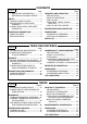
English CONTENTS Page IMPORTANT INFORMATION ............ 3 MEANINGS OF SIGNAL WORDS ..... 3 7 Page ASSEMBLY AND OPERATION ............... 10 APPLICATIONS .................................... 10 PRIOR TO OPERATION ....................... 10 HOW TO USE ....................................... 11 USING DRILL CHUCK, CHUCK ADAPTOR ......................................... 14 HOW TO USE THE CORE BIT ............. 15 8 MAINTENANCE AND INSPECTION ....... 17 FUNCTIONAL DESCRIPTION ....................
English IMPORTANT INFORMATION Read and understand all of the operating instructions, safety precautions and warnings in the Instruction Manual before operating or maintaining this power tool. Most accidents that result from power tool operation and maintenance are caused by the failure to observe basic safety rules or precautions. An accident can often be avoided by recognizing a potentially hazardous situation before it occurs, and by observing appropriate safety procedures.
English SAFETY GENERAL SAFETY RULES WARNING: Read and understand all instructions. Failure to follow all instructions listed below, may result in electric shock, fire and/or serious personal injury. SAVE THESE INSTRUCTIONS 1. Work Area (1) Keep your work area clean and well lit. Cluttered benches and dark areas invite accidents. (2) Do not operate power tools in explosive atmospheres, such as in the presence of flammable liquids, gases, or dust.
English 4. 5. 6. 7. (3) Avoid accidental starting. Be sure switch is off before plugging in. Carrying tools with your finger on the switch or plugging in tools that have the switch on invites accidents. (4) Remove adjusting keys or wrenches before turning the tool on. A wrench or a key that is left attached to a rotating part of the tool may result in personal injury. (5) Do not overreach. Keep proper footing and balance at all times.
English 8. Use right tool. Don’t force small tool or attachment to do the job of a heavy-duty tool. Don’t use tool for purpose not intended — for example — don’t use circular saw for cutting tree limbs or logs. 9. Never use a power tool for applications other than those specified. Never use a power tool for applications other than those specified in the Instruction Manual. 10. Handle tool correctly. Operate the tool according to the instructions provided herein. Do not drop or throw the tool.
English SPECIFIC SAFETY RULES AND SYMBOLS 1. Hold tools by insulated gripping surfaces when performing an operation where the cutting tool may contact hidden wiring or its own cord. Contact with a “live” wire will make exposed metal parts of the tool “live” and shock the operator. 2. Wear ear plugs when using the tool for extended periods. Prolonged exposure to high intensity noise can cause hearing loss. 3. NEVER touch the tool bit with bare hands after operation. 4.
English DOUBLE INSULATION FOR SAFER OPERATION To ensure safer operation of this power tool, HITACHI has adopted a double insulation design. “Double insulation” means that two physically separated insulation systems have been used to insulate the electrically conductive materials connected to the power supply from the outer frame handled by the operator. Therefore, either the symbol “ ” or the words and “Double insulation” appear on the power tool or on the nameplate.
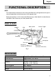
English FUNCTIONAL DESCRIPTION NOTE: The information contained in this Instruction Manual is designed to assist you in the safe operation and maintenance of the power tool. Some illustrations in this Instruction Manual may show details or attachments that differ from those on your own power tool. NAME OF PARTS Stopper Side Handle Grip Switch Trigger Front Cap Handle Selector Lever Housing Tail Cover Set Screw (Under the Tail Cover) Nameplate Dial Brush Cap (Inside the Tail Cover) Fig.
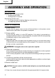
English ASSEMBLY AND OPERATION APPLICATIONS Rotation and hammering function 䡬 Drilling anchor holes 䡬 Drilling holes in concrete Hammering function only 䡬 Crushing concrete, chipping, digging, and squaring (by applying optional accessories) PRIOR TO OPERATION 1. Power source Ensure that the power source to be utilized conforms to the power source requirements specified on the product nameplate. 2. Power switch Ensure that the switch is in the OFF position.
English (2) To attach the tool (SDS max shank), insert it into the hole until it contacts the innermost end of the hole as illustrated in Fig. 2. If you continue to turn the tool with slight pressure, you can feel a spot where there is a hitch. At that spot, pull the grip to the direction of an arrow mark and insert the tool all the way until it hits the innermost end. Releasing the grip reverts the grip and secures the tool in place.
English CAUTION: Although this machine is equipped with a safety clutch, if the drill bit becomes bound in concrete or other material, the resultant stoppage of the drill bit could cause the machine body to turn in reaction. Ensure that the main handle and side handle are gripped firmly during operation. 2. How to chisel or crush (Fig. 5) By applying the tool tip to the chiseling or crushing position, operate the rotary hammer by utilizing its empty weight. Forcible pressing or thrusting is unnecessary.
English (1) Switching to “hammering” (a) Pull the selector lever, release lock and turn it counterclockwise. (b) Align ▲ of the selector lever with ▲ side of the undercover as on the illustrated in Fig. 7. (c) Push in the selector lever to lock it. NOTE: Turn the selector lever (do not pull it up) to check if it is completely locked and make sure that it does not turn. Undercover ▲ ▲ Selector Lever Fig. 7 䡬 䡩 ▲ (2) When fixing working positions of tools such as cold chisel, etc.
English 6. Warming up (Fig. 11) The grease lubrication system in this unit may require warming up in cold regions. Position the end of the bit so makes contact with the concrete, turn on the switch and perform the warming up operation. Make sure that a hitting sound is produced and then use the unit. CAUTION: When the warming up operation is performed, hold the side handle and the main body securely with both hands to maintain a secure grip and be careful not to twist your body by the jammed drill bit. 7.
English (1) Switching to “rotation + hammering” For switching to “rotation + hammering”, follow the same procedures mentioned in [3. When drilling at “rotation + hammering”] in Page 12. (2) Attaching chuck adaptor to drill chuck (Fig. 14) Drill SDS max Chuck (a) Attach the chuck adaptor to the drill Grip Shank chuck. Chuck (b) The SDS max shank of the chuck Adaptor adaptor is equivalent to the drill bit. Fig. 14 Therefore, follow the same procedure as [6.
English (2) Mount the core bit shank to the rotary hammer. (Fig. 16) (3) Insert the center pin into the guide plate until it stops. (4) Engage the guide plate with the core bit, and turn the guide plate to left or right so that it does not fall even if it faces downward. (Fig. 17) 2. How to bore (Fig. 18) (1) Connect the plug to the receptacle. (2) A spring is installed in the center pin. Push it lightly to the wall or the floor straight.
English MAINTENANCE AND INSPECTION WARNING: Be sure to switch power OFF and disconnect the plug from the receptacle during maintenance and inspection. 1. Inspecting the drill bits Since use of a dull tool will cause motor malfunctioning and degraded efficiency, replace the drill bit with a new one or resharpening without delay when abrasion is noted. 2. Inspecting the mounting screws Regularly inspect all mounting screws and ensure that they are properly tightened.
English 䡬 Replacing carbon brushes: (For parts name, refer to Fig. 1) Loosen the two set screws and remove the tail cover. Remove the brush caps and carbon brushes. After replacing the carbon brushes, tighten the brush caps securely and to install the tail cover with securely tightening two set screws. 5. How to replase grease This machine is full air-tight construction to protect against dust and to prevent lubricant leakage. Therefore, the machine can be used without lubrication for long periods.
English ACCESSORIES WARNING: Accessories for this power tool are mentioned in this Instruction Manual. The use of any other attachment or accessory can be dangerous and could cause injury or mechanical damage. NOTE: Accessories are subject to change without any obligation on the part of the HITACHI. STANDARD ACCESSORIES (1) (2) (3) (4) (5) (6) Case (Molded plastic) (Code No. 313097) ............................................................. 1 Side Handle (Code No. 313078) .............................
English 2. Anchor hole drilling (Rotation + Hammering) Adaptor for SDS-plus shank bit (1) Drill Bit (SDS-plus shank) (2) Adaptor for SDS-plus shank bit (SDS max shank) Code No. 313465 3. Large-dia. hole boring (Rotation + Hammering) (Guide plate) (1) Center pin (2) Core bit Code No. 985388 955169 Code No. 955165 External dia. 2" (50 mm) 4-1/8" (105 mm) (3) Core bit shank (SDS max shank) Code No. 313467 4. Drilling holes....
English 7. Groove digging and edging (Hammering) (1) Cold chisel Overall length 11" (280 mm) 15-3/4" (400 mm) Code No. 313473 313474 8. Asphalt cutting (Hammering) (1) Cutter Overall length 15-3/4" (400 mm) Width 1-31/32" (50 mm) Code No. 313473 9. Digging (1) Scoop Code No. 313476 10. Surface Roughing (Hammering) (1) Bushing Tool (2) Shank Overall length 8-21/32" (220 mm) Code No. 313477 Code No. 313479 11. Tamping (Hammering) (1) Rammer Code No.
Français INFORMATIONS IMPORTANTES Lire et comprendre toutes les instructions de fonctionnement, les précautions de sécurité et les avertissements dans ce mode d’emploi avant d’utiliser ou d’entretenir cet outil motorisé. La plupart des accidents causés lors de l’utilisation ou de l’entretien de l’outil motorisé proviennent d’un non respect des règles ou précautions de base de sécurité.
Français SECURITE REGLES GENERALE DE SECURITE AVERTISSEMENT: Lire et coxmprendre toutes les instructions. Un non respect de toutes les instructions ci-dessous peut entraîner une électrocution, un incendie et/ou de sérieuses blessures personnelles. CONSERVER CES INSTRUCTIONS 1. Zone de travail (1) Garder la zone de travail propre et bien éclairée. Les établis mal rangés et les zones sombres invitent aux accidents.
Français (2) S’habiller correctement. Ne pas porter des vêtements larges ou des bijoux. Attacher les cheveux longs. Tenir ses cheveux, vêtements et ses gants éloignés des parties mobiles. Les vêtements larges, les bijoux et les cheveux longs peuvent se prendre dans les parties mobiles. (3) Eviter tout démarrage accidentel. S’assurer que le l’interrupteur d’alimentation est sur la position d’arrêt avant de brancher la machine.
Français 5. Réparation (1) La réparation de l’outil ne doit être réalisée uniquement par un réparateur qualifié. Une réparation ou un entretien réalisé par un personnel non qualifié peut entraîner des risques de blessures. (2) Lors de la réparation d’un outil, utiliser uniquement des pièces de rechange identiques. Suivre les instructions de la section d’entretien de ce mode d’emploi.
Français 15. Utiliser l’outil motorisé à la tension nominale. Utiliser l’outil motorisé à la tension spécifiée sur sa plaque signalétique. Si l’on utilise l’outil motorisé avec une tension supérieure à la tension nominale, il en résultera une rotation anormalement trop rapide du moteur et cela risque d’endommager l’outil et le moteur risque de griller. 16. Ne jamais utiliser un outil défectueux ou qui fonctionne anormalement.
Français DOUBLE ISOLATION POUR UN FONCTIONNEMENT PLUS SUR Pour assurer un fonctionnement plus sûr de cet outil motorisé, HITACHI a adopté une conception à double insolation. “Double isolation” signifie que deux systèmes d’isolation physiquement séparés ont été utilisés pour isoler les matériaux conducteurs d’électricité connectés à l’outil motorisé à partir du cadre extérieur manipulé par l’utilisateur.
Français DESCRIPTION FONCTIONNELLE REMARQUE: Les informations contenues dans ce mode d’emploi sont conçues pour assister l’utilisateur dans une utilisation sans danger et un entretien de l’outil motorisé. Certaines illustrations dans ce mode d’emploi peuvent montrer des détails ou des accessoires différents de ceux de l’outil motorisé utilisé.
Français ASSEMBLAGE ET FONCTIONNEMENT APPLICATIONS Fonction de rotation et de percussion 䡬 Perçage de trous d’ancrage 䡬 Perçage de trous dans béton Fonction de percussion uniquement 䡬 Broyage du béton, burinage, creusage et équarrissage (par application des accessoires optionnels) AVANT L’UTILISATION 1. Source d’alimentation S’assurer que la source d’alimentation qui doit être utilisée est conforme à la source d’alimentation requise spécifiée sur la plaque signalétique du produit. 2.
Français (2) Pour fixer l’outil (tige SDS max), l’insérer dans l’orifice jusqu’à ce qu’il touche l’extrémité intérieure de l’orifice comme indiqué sur la Fig. 2. Si l’on continue à tourner l’outil en exerçant une légère pression, l’on sentira un endroit où il y a un obstacle. A cet endroit, tirer l’attache coulissante dans le sens de la flèche et insérer l’outil à fond jusqu’à ce qu’il touche l’extrémité intérieure. Le fait de relâcher l’attache coulissante l’inverse et fixe l’outil en place.
Français PRECAUTION: Bien que cette machine soit équipée d’un cran de sécurité, si la mèche est prise dans le béton ou autre matériel l’arrêt de son fonctionnement pourrait faire tourner le corps de la machine. Tenir fermement la poignée principale et la poignée latérale pendant le fonctionnement. 2. Comment buriner ou broyer (Fig. 5) En appliquant l'outil sur la position de burinage ou de broyage, faire fonctionner le marteau rotatif en utilisant son propre poids.
Français (1) Commutation sur “percussion” (a) Tirer sur le sélecteur, libérer le verrouillage et le tourner dans le sens inverse des aiguilles d’une montre. (b) Aligner ▲ du sélecteur sur ▲ sur le du dessous, comme indiqué côté à la Fig. 7. (c) Appuyer sur le sélecteur pour le verrouiller. REMARQUE: Le tourner (ne pas tirer dessus) pour voir s’il est bien verrouillé à fond et vérifier qu’il ne tourne pas. Cache inférieur ▲ ▲ Sélecteur Fig.
Français 6. Préchauffage (Fig. 11) Le système de graissage de l’outil risque de devoir être préchauffé dans les régions froides. Placer l’extrémité de la mèche de façon qu’elle entre en contact avec le béton, enclencher l’interrupteur et effectuer une opération de préchauffage. Bien s’assurer que l’outil fait entendre un bruit de heurt, puis utiliser l’outil.
Français (1) Commutation sur “rotation + percussion” Pour commuter sur “rotation + percussion”, procéder comme indiqué au point [3. Perçage en “rotation + percussion”]. (2) Fixation du raccord de mandrin sur le mandrin porte-foret (Fig. 14) Mandrin Tige SDS (a) Fixer le raccord de mandrin sur le porteAttache max mandrin porte-foret. foret coulissante Raccord de (b) La tige SDS max du raccord de mandrin mandrin est l’équivalent du foret de perçage. En conséquence, pour la Fig.
Français (2) Monter la queue de couronne sur le marteau rotatif à percussion. (Fig. 16) (3) Introduire la guijon central dans la plaque de guidage jusqu’à ce qu’il arrête. (4) Engager la plaque de guidage dans la couronne et tourner la plaque de guidage à gauche ou à droite de manière à ce qu’elle à ce qu’elle ne puisse pas tomber, même si elle orientée vers le bas. (Fig. 17) Fig. 16 2. Perçage (Fig. 18) (1) Brancher la perceuse. (2) Un ressort est placé dans le goujon central.
Français ENTRETIEN ET INSPECTION AVERTISSEMENT: S’assurer de mettre l’interrupteur d’alimentation sur la position OFF et de déconnecter la fiche de la prise secteur avant l’entretien et l’inspectio. 1. Contrôle du foret de perçage Etant donné que l’utilisation d’une mèche usée entraînera un mauvais fonctionnement du moteur et une diminution de l’efficacité, remplacez la mèche usée par une neuve ou aiguisez-la immédiatement et dès que vous notez une certaine usure. 2.
Français 䡬 Remplacement du balais en carbone Desserrer la vis de fixation et enlever le couvercle de la queue. Enlever la chapeau de balai et la balai en carbone. Après avoir remplacé le balai en carbone, serrer fermement le chapeau du balai et installer le couvercle avec deux vis de fixation. 5. Comment remplacer la graisse Cette machine est de contruction entièrement hermétique pour la protéger contre la poussière et pour éviter les fuites de lubrifiant.
Français ACCESSOIRES AVERTISSEMENT: Les accessoires pour cet outil motorisé sont mentionnés dans ce mode d’emploi. L’utilisation de tout autre attachement ou accessoire peut être dangereux et peut causer des blessures ou des dommages mécaniques. REMARQUE: Les accessoires sont sujets à changement sans obligation de la part de HITACHI. ACCESSOIRES STANDARD (1) (2) (3) (4) (5) (6) Valise (Plastique) (No. de code 313097) ................................................................ 1 Poignée latérale (No.
Français 2. Perçage de trous d’ancrage (Rotation + Percussion) Adaptateur pour tige SDS plus (1) Mèche (Tige SDS plus) (2) Adaptateur pour tige SDS plus (Tige SDS max) No. de code 313465 3. Perçage de trous à large diamètre (Rotation + Percussion) (plaque de guidage) No. de code 985388 955169 (1) Goujon central No. de code 955165 (2) Couronne (3) Queue de cournne (Tige SDS max) Diamètre extérieur No. de code 2" (50 mm) 313467 4-1/8" (105 mm) 4. Perçage de trous.
Français 7. Creusage de rainures et cassure des angles (Percussion) (1) Ciseau à froid Longueur totale 11" (280 mm) 15-3/4" (400 mm) No. de code 313473 313474 8. Coupage d’asphalte (Percussion) (1) Fraise Longueur totale 15-3/4" (400 mm) Largeur 1-31/32" (50 mm) No. de code 313473 9. Puisage (Percussion) (1) Scoop No. de code 313476 10. Dégrossissage (Percussion) (1) Boucharde (2) Queue Longueur totale No. de code 313477 8-21/32" (220 mm) No. de code 313479 11.
Español INFORMACIÓN IMPORTANTE Antes de utilizar o realizar cualquier trabajo de mantenimiento de esta herramienta eléctrica, lea y comprenda todas las instrucciones de operación, las precauciones de seguridad, y las advertencias de este Manual de instrucciones. La mayoría de los accidentes producidos en la operación y el mantenimiento de una herramienta eléctrica se deben a la falta de observación de las normas o precauciones de seguridad.
Español SEGURIDAD NORMAS GENERALES DE SEGURIDAD ADVERTENCIA: Lea y entienda todas las instrucciones. Si no sigue las instrucciones indicadas a continuación, pueden producirse descargas eléctricas, incendios, y/o lesiones serias. GUARDE ESTAS INSTRUCCIONES. 1. Área de trabajo (1) Mantenga el área de trabajo limpia y bien iluminada. Los bancos de trabajo desordenados y las áreas obscuras pueden conducir a accidentes.
Español de medicamentos ni de alcohol. Un descuido al utilizar la herramienta eléctrica puede resultar en una lesión seria. (2) Vístase adecuadamente. No utilice ropa floja ni joyas. Si tiene pelo largo, recójaselo. Mantenga su pelo, ropa, y guantes alejados de las partes móviles. La ropa floja, las joyas, o el pelo largo pueden engancharse en las partes móviles. (3) Evite la puesta en marcha accidental.
Español 5. Servicio de reparación (1) El servicio de reparación deberá realizarlo solamente personal cualificado. El servicio de mantenimiento o de reparación realizado por personal no cualificado podría resultar en el riesgo de lesiones. (2) Para el servicio de mantenimiento o reparación de una herramienta, utilice solamente piezas de repuesto idénticas. Siga las instrucciones de la sección de mantenimiento de este manual.
Español La utilización e una herramienta eléctrica con una tensión superior a la nominal podría resultar en revoluciones anormalmente altas del motor, en el daño de la herramienta, y en la quemadura del motor. 16. No utilice nunca una herramienta defectuosa o que funcione anormalmente. Si la herramienta parece que funciona anormalmente, produciendo ruidos extraños, etc., deje inmediatamente de utilizarla y solicite su arreglo a un centro de reparaciones autorizado por Hitachi. 17.
Español AISLAMIENTO DOBLE PARA OFRECER UNA OPERACIÓN MÁS SEGURA Para garantizar una operación más segura de esta herramienta eléctrica, HITACHI ha adoptado un diseño de aislamiento doble. “Aislamiento doble” significa que se han utilizado dos sistemas de aislamiento físicamente separados para aislar los materiales eléctricamente conductores conectados a la fuente de alimentación del bastidor exterior manejado por el operador.
Español DESCRIPCIÓN FUNCIONAL NOTA: La información contenida en este Manual de instrucciones ha sido diseñada para ayudarle a utilizar con seguridad y mantener esta herramienta eléctrica. Algunas ilustraciones de este Manual de Instrucciones pueden mostrar detalles o accesorios diferentes a los de la propia herramienta eléctrica.
Español MONTAJE Y OPERACIÓN APLICACIONES Función de rotación y golpeteo 䡬 Perforación de orificios de anclaje 䡬 Perforación de orificios en hormigón Función de martilleo solamente 䡬 Trituración de hormigón, cincelado, excavación y escuadreo (utilizando accesorios opcionales) ANTES DE LA OPERACIÓN 1. Fuente de alimentación Cerciórese de que la fuente de alimentación que vaya a utilizar cumpla los requisitos indicados en la placa de características del producto. 2.
Español (2) Para fijar la herramienta (espiga SDS max), insértela en el orificio hasta que entre en contacto con el extremo interior del mismo, como se muestra en la Fig. 2. Si continúa girando la herramienta con una ligera presión, podrá sentir un punto en el que note un obstáculo. En tal punto, tire del mango lateral en el sentido de la marca de flecha e inserte la herramienta completamente hasta que entre en contacto con el extremo interior.
Español PRECAUCIÓN: Aunque este aparato se equipa con un embrague de seguridad, si se atasca la barrena de taladrar en el hormigón u otro material semejante, puede pasar que, al atascarse la barrena, el cuerpo del martillo gire en dirección opuesta. Asegurarse entonces de que el mango principal y el lateral están bien empuñados durante el uso de esta herramienta. 2. Forma de picar o romper (Fig.
Español (1) Cambio a “martilleo” (a) Tire de la palanca selectora, desbloquéela, y gírela hacia la derecha. (b) Alinee ▲ de la palanca selectora con de la cubierta inferior, ▲ del lado como se muestra en la Fig. 7. (c) Empuje la palanca selectora para bloquearla Cubierta inferior ▲ ▲ Fig. 7 NOTA: Gire la palanca selectora (no tire de ella hacia arriba) para comprobar si está completamente bloqueada y cerciorarse de que no gire.
Español 6. Calentamiento (Fig. 11) El sistema de lubricación de esta unidad puede requerir calentamiento en ciertas regiones. Coloque el extremo de la broca de forma que entre en contacto con el hormigón, ponga en ON el interruptor de alimentación principal de la unidad, y realice la operación de calentamiento. Cerciórese de que se produzca un sonido de martilleo, y después utilice la unidad.
Español (1) Cambio a “rotación + martilleo” Para cambiar a “rotación + martilleo”, realice los mismos procedimientos que los mencionados en [3. Cuando taladre con “rotación + martilleo”]. (2) Fijación del adaptador para portabarrenas al portabarrenas (Fig. 14) Portabrocas Espiga (a) Fije el adaptador para Sujetador SDS max portabarrenas al portabarrenas. Adaptador del (b) La espiga SDS max del adaptador portabrocas para portabarrenas es equivalente a la barrena. Por lo tanto, para la Fig.
Español (2) Montar la espiga de la barrena tubular en el martillo giratorío. (Fig. 16) (3) Insertar el pasador central en la placa guía hasta que se pare. (4) Unir la placa guía con la barrena tubular y girar la placa guía hacia la izquierda o hacia la derecha de forma que no se caiga a pesar de estar indicando hacia abajo. (Fig. 17) Fig. 16 2. Modo de taladrar (Fig. 18) (1) Conectar el enchufe a la toma de alimentación. (2) El pasador central se ha instalado un resorte.
Español MANTENIMIENTO E INSPECCIÓN ADVERTENCIA: Antes de realizar el mantenimiento o la inspección de la amoladora, cerciórese de desconectar la alimentación y de desenchufar el cable de alimentación del tomacorriente. 1. Inspeccionar la broca de taladro Debido a que el uso de brocs desafiladas pueden causar mal funcionamiento del motor y desmejorar la eficacia del taladro, hay que reemplazar las brocas en malas condiciones por nuevas o afilarlas de inmediato al advertir abrasión. 2.
Español NOTA: Utilice las escobillas HITACHI Núm. 73 indicadas en la Fig. 20. 䡬 Cambio de escobillas de carbón Quitar la cubierta de cola y luego aflojar el tornillo de fijación. Aflojando la tapa de escobilla, pueden quitarse las escobillas de carbón, al colocar las escobillas, apretar firmemente la tapa de escobillas y recolocar la cubierta de con dos tornillos. 5. Cambio de grasa Esta máquina es de construcción completamente cerrada, para evitar que entre polvo y haya fugas de lubricante.
Español ACCESORIOS ADVERTENCIA: Los accesorios para esta herramienta eléctrica se mencionan en este Manual de instrucciones. La utilización de otros accesorios puede resultar peligrosa y causar lesiones o daños mecánicos. NOTA: Los accesorios están sujetos a cambio sin ninguna obligación por parte de HITACHI. ACCESORIOS ESTÁNDAR (1) (2) (3) (4) (5) (6) Caja (Plástica) (Núm. de código 313097) .............................................................. 1 Mango lateral (Núm. de código 313078) ...........
Español 2. Perforación de orificio de anclaje (Rotación + Martilleo) Adaptador para barrena de espiga SDS-plus (1) Barrena (SDS plus vástago) (2) Adaptador para barrena de espiga SDS-plus (Espiga SDS max) Núm. de código 313465 3. Perforación de orificio de diámetro grande (Rotación + Martilleo) (2) Barrena (3) Espiga de barrena (1) Pasador tubular (Espiga SDS max) contral Núm. de código Núm. de código Diámetro externo Núm. de código 985388 2" (50 mm) 955165 313467 955169 4-1/8" (105 mm) (Placa guía) 4.
Español 7. Excavar, ranurado y rebordes (Martilleo) (1) Cortafrio Largo total 11" (280 mm) 15-3/4" (400 mm) Núm. de código 313473 313474 8. Corte de asfalto (Martilleo) (1) Cortadora Largo total 15-3/4" (400 mm) Anchura Núm. de código 1-31/32" (50 mm) 313473 9. Trabajos con cuchara (Martilleo) (1) Cuchara Núm. de código 313476 10. Desbastadora de superficies (Martilleo) (1) Desbastadora Núm. de código 313477 (2) Barrena Largo total Núm. de código 8-21/32" (220 mm) 313479 11.
Español 60
Español Item No. Part Name Item No.
Español Item No. Part Name 83 84 85 86 87 88 89 90 91 92 93 94 95 96 97 98 99 100 101 102 103 104 105 106 107 108 109 110 111 112 113 114 115 116 117 118 119 120 121 122 123 Washer M4 Nylock Hex. Socket Hd. Bolt M4×12 Lever Spring Sleeve Nylock Bolt (W/Flange) M5×25 Ball Bearing (6202VVCMPS2S) Dust Washer (B) O-Ring Fan Armature Ass’y Hex. Hd.
Español 63
WARNING: Some dust created by power sanding, sawing, grinding, drilling, and other construction activities contains chemicals known to the State of California to cause cancer, birth defects or other reproductive harm. Some examples of these chemicals are: ● Lead from lead-based paints, ● Crystalline silica from bricks and cement and other masonry products, and ● Arsenic and chromium from chemically-treated lumber. Your risk from these exposures varies, depending on how often you do this type of work.