
Manual


English
NOTE:
The information contained in this Instruction Manual is designed to assist you in
the safe operation and maintenance of the power tool,
Some illustrations in this Instruction Manual may show details or attachments
that differ from those on your own power tool.
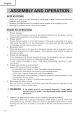
NAME OF PARTS
Push Button
Gear Cover
\
Packing Gland
Housing Handle
/I
/ /
"- Switch Lever
Locking Button
[When the switch has locking mechanism]
Depressed
Center Wheel
SPECIFICATIONS
Wheel Guard
Fig. 1
\\
\
Side Handle
Motor
Power Source
Current
No-Load Speed
Wheel Size:
external diam.
hole diam.
Weight
Single-Phase Series Commutator Motor
Single-Phase 115V AC 60Hz
+
1t.0A
10,000/min
i
5"(125mm) t
7/8"(22mm)
j 6.2 Ibs(2.8 kg)