INSTRUCTIONS-PARTS LIST 308398 Rev. P This manual contains important warnings and information. READ AND KEEP FOR REFERENCE. INSTRUCTIONS 5.5 HORSEPOWER, GASOLINE–POWERED GM7000 Airless Paint Sprayer 3000 psi (207 bar, 21 MPa) Maximum Working Pressure Model 231326, Series D This is a basic sprayer without a hose or a gun.
Table of Contents Warnings . . . . . . . . . . . . . . . . . . . . . . . . . . . . . . . . . . . . . 2 Component Identification and Function . . . . . . . . . 5 Setup . . . . . . . . . . . . . . . . . . . . . . . . . . . . . . . . . . . . . . . . 6 Fueling . . . . . . . . . . . . . . . . . . . . . . . . . . . . . . . . . . . . . . . 8 Startup . . . . . . . . . . . . . . . . . . . . . . . . . . . . . . . . . . . . . . . 8 Maintenance . . . . . . . . . . . . . . . . . . . . . . . . . . . . . . . . .
WARNING INJECTION HAZARD Spray from the gun, leaks or ruptured components can inject fluid into your body and cause extremely serious injury, including the need for amputation. Fluid splashed in the eyes or on the skin can also cause serious injury. D Fluid injected into the skin may look like just a cut, but it is a serious injury. Get immediate medical attention. D Do not point the gun at anyone or at any part of the body. D Do not put your hand or fingers over the spray tip.
WARNING FIRE AND EXPLOSION HAZARD Improper grounding, poor ventilation, open flames or sparks can cause a hazardous condition and result in a fire or explosion and serious injury. D If there is any static sparking or you feel an electric shock while using this equipment, stop spraying immediately. Do not use the equipment until you identify and correct the problem. D Provide fresh air ventilation to avoid the buildup of flammable fumes from solvents or the fluid being sprayed.
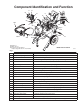
Component Identification and Function A B M K 51 C D N 53 202 4 L J H 20 G F 1 71 204 203 E 47 28 202 Main hose 203 Whip end hose 204 Contractor gun with RAC IV DripLess tip guard and 517 size SwitchTip Model 231327 shown 03467C Fig. 1 A Pressure Control Switch ON/OFF, enables/disables clutch function B Pressure Adjusting Knob Controls fluid outlet pressure C Air Cleaner* Filters air entering the carburetor D Fuel Tank* Holds 0.95 gallons (3.
Setup NOTE: A 55 gallon (200 liter) suction tube kit, Part No. 236951, is available. WARNING If you are supplying your own hoses and spray gun, be sure the hoses are electrically conductive, that the gun has a tip guard, and that each part is rated for at least 3000 psi (207 bar, 21 MPa) Maximum Working Pressure. This is to reduce the risk of serious injury caused by static sparking, fluid injection or over-pressurization and rupture of the hose or gun. CAUTION 2. Two gun hookup.
Setup 5. Be sure your system is properly grounded before operating it. Read and follow the warning section, FIRE OR EXPLOSION HAZARD, on page 4. Use the grounding wire and clamp (47) whenever the sprayer is used as a stationary unit. 9. Keep the sprayer upright and level during operation and whenever it is being moved. See the last CAUTION on page 9. 6. Fill the gas tank. See Fueling, page 8. 7. Flush the pump to remove the lightweight oil which was left in the pump to protect it from rust. L a.
Fueling WARNING Gasoline is extremely flammable and explosive under certain conditions. Always turn the engine switch (K) to off before refueling. Refuel in a well–ventilated area. Do not smoke or allow flames or sparks in the area where the engine is refueled or where the gasoline is stored. Do not overfill the tank. Make sure the gas fill cap (L) is securely closed after refueling. Be careful not to spill fuel when fueling. Fuel vapor or spilled fuel can ignite.
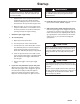
Startup WARNING A rope which recoils too quickly may hit someone and cause serious injury. The rope could also jam in recoil assembly. f. Hold the frame of the sprayer with one hand and pull the starter rope rapidly and firmly. Continue holding the rope as you let it return. Pull and return the rope until the engine starts. g. Open the choke as soon as the engine starts, except in cold weather. In cold weather, leave the choke closed for 10 to 30 seconds before opening it to keep the engine running. 7.
Maintenance WARNING INJECTION HAZARD To reduce the risk of serious injury, whenever you are instructed to relieve pressure, follow the Pressure Relief Procedure on page 10. DAILY: sary. Check the engine oil level and fill as neces- DAILY: Check hose for wear and damage. DAILY: Check gun safety for proper operation. DAILY: tion. Check pressure drain valve for proper opera- DAILY: Check and fill the gas tank. AFTER THE FIRST 20 HOURS OF OPERATION Drain the oil and refill with clean oil.
Flushing When using oil–based paint, flush out the mineral spirits with the paint to be sprayed. When to Flush 1. New Sprayer. This sprayer was factory tested in lightweight oil,which was left in to protect the pump parts. How to Flush Before using water–base paint, flush with mineral spirits, followed by a soapy water flush, and then a clean water flush.
Flushing 6. Follow Startup on page 8. Keep the gun triggered until clean solvent comes from the nozzle. Release the trigger and lock the gun trigger safety. NOTE: For two guns, unlock the gun trigger safety on the second gun and trigger that gun until clean solvent comes from the nozzle. Flush the first gun and then the second gun at least one more time. 10. Unscrew the filter bowl and reinstall the clean screen. Reinstall the bowl, hand tight only. 11. Follow Storage or Changing Colors, to the left.
Troubleshooting WARNING INJECTION HAZARD To reduce the risk of serious injury, including fluid injection or splashing in the eyes or on the skin, or injury from moving parts, always follow the Pressure Relief Procedure Warning, page 10, before checking, adjusting, cleaning or shutting down the sprayer. Disconnect the spark plug! Check everything in the chart before disassembling the sprayer. PROBLEM CAUSE SOLUTION The engine or sprayer won’t start start. The engine switch is not on.
PROBLEM CAUSE SOLUTION The pump output is low on the upstroke. upstroke The inlet screen (31 or 23a) is clogged. Clean the screen. The piston ball (425) is not seating. Service the piston ball–check. See manual 307806. The piston packings are worn or damaged. Replace the packings. See manual 307806. The gasket (417) in the displacement pump is worn or damaged. Replace the gasket. See manual 307806. The inlet screen (31 or 23a) is clogged. Clean the screen.
Bearing Housing & Connecting Rod WARNING INJECTION HAZARD To reduce the risk of serious injury, whenever you are instructed to relieve pressure, follow the Pressure Relief Procedure on page 10. NOTE: Steps 1 to 13 refer to Fig. 7. 1. Relieve pressure. 2. Remove the screws (68) and the front cover (23). 13. Align the connecting rod with the crank (A) and carefully align the locating pins (F) in the drive housing (20) with the holes in the bearing housing (21).
Drive Housing WARNING INJECTION HAZARD To reduce the risk of serious injury, whenever you are instructed to relieve pressure, follow the Pressure Relief Procedure on page 10. NOTE: Refer to Fig. 8 for this procedure. 1. Relieve pressure. 2. Remove the bearing housing. Follow Steps 1 to 8 on page 15. 3. Remove the two screws (24) and lockwashers (29) from the drive housing (20). 4. Remove the four screws (17) and lockwashers (29) from the pinion housing (19). 5.
Drive Housing 17 29 20a 19 B 20 73 21 74 29 24 17 29 23 19d 20b 18 68 112 113 114 Fig.
Pinion, Clutch, Clamp, Field, & Engine Disassembling these parts can start from the pinion housing, or from the clutch if no pinion service is needed. If starting from the pinion housing, first follow Steps 3 to 5 of DRIVE HOUSING, on page 16, and then continue with the procedure below. If starting from the clutch, see page 20. CAUTION Do not lose the thrust ball (19d). Refer to the CAUTION on page 16 for more information. NOTE: To disassemble the pinion, go to page 19.
Pinion Housing 6 1 19k 2 1.45 in 19n 19b 19p 1 The back of the pinion housing (19a). 2 Slide the pinion assembly in here. 3 Lubricate the exterior. 4 Lubricate the inner and outer diameters. 5 Lubricate the teeth. 6 This is a cutaway view of the pinion housing (19a). 19j** 3 19m** 19c 19h** 19g** 4 5 19d Fig. 10 3 19e 19a 03475A If purchasing parts separately, use these instructions. Disassemble as far as needed for the parts being replaced. Repairing the Pinion NOTE: Refer to Fig.
Clutch 4. Tap lightly on the back of the bearing housing (21) with a plastic mallet to loosen the assembly (D) from the clutch housing. Pull the assembly away. WARNING INJECTION HAZARD To reduce the risk of serious injury, whenever you are instructed to relieve pressure, follow the Pressure Relief Procedure on page 10. 5. The armature (4a) was removed with the pinion housing. Remove the armature from the pinion hub. 6. There are two procedures to remove the rotor (4b).
Field & Wiring Harness NOTE: Refer to Fig. 13. 1. Loosen the four setscrews (12) holding the field (6) to the clutch housing (2). 2. Pull off the field. 12 3. Pull the plastic caps (B) off the wire screws (98) in both places on the field. Loosen the screws and release the wires (96). 2 4. Skip ahead to Reassembly, page 24, step 4. or continue on page 21. 6 96 B 98 Fig. 13 03479 Clamp NOTE: A standard steering wheel puller and two 1/4–28 x 3 or 4 in. long screws are required to remove the clamp.
Clutch Housing NOTE: Refer to Fig. 15. 2 1. Remove the four capscrews (8) and lockwashers (9) which hold the clutch housing (2) to the engine. 13 9 8 2. Remove the capscrew (15), lockwasher (80) and washer (99) from beneath the mounting plate (D). 3. Remove the engine key (13). 4. Pull off the clutch housing (2). D 15 5. Skip ahead to Reassembly, page 24, step 1. Fig.
Engine 1. Remove the Pinion Housing, Clutch, Field and Wiring Harness, Clamp and Clutch Housing, as instructed on pages 18 and 20 through 22. 2. See Fig. 16 and17. Disconnect the red wire from the engine lead (B). Disconnect the black and white wires from the field. Loosen the clamp (97). Pull the wires carefully through the grommets (66) before removing the engine. Remove the two locknuts (111) and then pull the screws (14) out of the base of the engine. 3.
Reassembly 1. Install the clutch housing (2), capscrews (8) and lockwashers (9) on the engine. See Fig. 18. 2. Install the engine shaft key (13). See Fig. 18. 3. Press the clamp (3) onto the engine shaft (A). Maintain the 1.99 "0.01 in. (50.55 "0.25 mm) dimension shown in Fig. 19. 1 The face of the housing. 2 1.99 "0.01 in. (50.55 "0.25 mm). 3 Torque the screws to 125 "10 in-lb (14 "1.1 N m) 1 To check the dimension, place a rigid, straight steel bar (B) across the face of the clutch housing (2).
Reassembly 6. Be sure the face of the rotor (4b) and the field are free of all oil and contaminants. Remove any burrs on the outside edge of the rotor. Install the rotor, lockwashers (11) and capscrews (16). Torque the capscrews to 125 "10 in-lb (14 "1.1 N m). See Fig. 20. 7. Be sure the face of the armature (4a) is clean. Assemble the armature to the shaft in the pinion housing (19). A retaining ring located within the armature makes it difficult to assemble these parts.
Pressure Control Replacement INJECTION HAZARD To reduce the risk of serious injury, whenever you are instructed to relieve pressure, follow the Pressure Relief Procedure on page 10. 1. Relieve pressure. 63 76 WARNING TO FILTER A A 2 1 To the pump. 2 To the filter. 1 2. Disconnect both hoses at the pressure control while holding the fitting or elbow (A) firmly. See the CAUTION, below. Note the original location of each hose to be sure you reassemble them correctly at the end of this procedure.
Displacement Pump Repairing the pump. WARNING INJECTION HAZARD To reduce the risk of serious injury, whenever you are instructed to relieve pressure, follow the Pressure Relief Procedure on page 10. Removing the pump. (See Fig. 23.) 1. Relieve pressure. 2. Flush the pump. See page 11 3. Hold the intake valve (423) with a wrench and unscrew the suction tube (30). Remove the hose (59). Remove the spring clips (112,114) and drain hose (113). 4. Push the retaining spring (26) up.
Parts Drawing – Basic Sprayer Model 231326 DETAIL 17 Ref 36 29 1 Label 2 See the detail.. 3 See page 34 for the parts. 4 See manual 307806 for the parts.
Parts List – Basic Sprayer Ref No. Part No. Description 1 2 3 4 108802 183397 183517 236568 ENGINE 1 CLUTCH HOUSING 1 CLAMP, mounting, rotor 1 CLUTCH ASSEMBLY Includes items 4a and 4b 1 .ARMATURE 1 .
Parts Drawing – Lo-Boy Sprayer DETAIL Model 231800 Ref 36 4 40 45 37 46 39 Ref 35 3 133 132 A A 142 36 1 101 141 1 12 13 10 11 2 2 9 6 14 3 7 49 6 66 47 11 16 96 98 4b 15 56 11 16 4a 1 Label 2 See the detail, above. 3 See page 32 for the parts. 4 See page 35 for the parts.
Parts List – Lo-Boy Sprayer Ref No. Part No.
Parts Drawing – Lo-Boy Sprayer Model 231800 63 76, 77 1 5 59 51 B 17 29 19 06871 117 79 111 56 97 9 3 18 20a 39 53 102 1 20 22 21 25 Ref 34 74 A 73 17 29 24 Ref 19d 20b 23 69 50a{ 68 B 87 59 29 50 26 A 27 50b{ 31 28 95 34 1 Label 2 See the detail, above. 3 See page 34 for the parts. 4 See manual 307806 for the parts. 5 See page 35 for the parts.
Parts List – Lo-Boy Sprayer Ref No. Part No. Description 9 17 100214 101864 LOCKWASHER, 5/16 inch CAPSCREW, socket head, 5/16–18 x 1 inch GEAR REDUCER PINION HOUSING ASSEMBLY See parts on page 34 DRIVE HOUSING Includes items 20a to 20c .WASHER, bronze .BALL, sst .
Parts List & Drawing – Complete Sprayer 204 Models 231327 and 231382 GM7000 Airless Paint Sprayer Includes items 201 to 205 203 Ref No. Part No. Description 201 231326 GM7000 Basic Sprayer See parts list on page 29 1 GM7000 Lo-Boy Sprayer See parts list on pages 31 and 33 1 HOSE, grounded, nylon; 3/8 inch ID; cpld 3/8 npsm(fbe); 50 foot (15 m); spring guards both ends 1 HOSE, grounded, nylon; 3/16 inch ID; cpld 1/4 npsm(m) x 1/4 npsm(f) swivel; 3 foot (0.
Parts List – Pressure Control Basic Pressure Control for the GM7000 Sprayers Ref No. Part No. Description 301 302 303 304 305 306 307 308 309 310 239056 107251 112610 100020 189095 112614 105679 107255 105659 236352 ENGINE CONTROL BOARD SCREW, panhead, 10–24 x 1 inch SCREW, panhead, 10–24 x 2 inch LOCKWASHER, No. 10 HOUSING, PLUG TOGGLE SWITCH GUARD BOOT POTENTIOMETER, pressure adjustment SEAL 311 108358 Qty 1 2 2 4 1 1 1 1 1 1 1 Parts Drawing – Pressure Control Ref No. Part No.
Technical Data Engine . . . . . . . . . . . . . . . . . . . . . . . . . . 5.5 horsepower, Honda Maximum working pressure . . . . 3000 psi (207 bar, 21 MPa) Noise Level Sound power . . . . . . . . . . . . . . . . . . . . . . . . . . . . . . . . . 105 dBa per ISO 3744 Sound pressure . . . . . . . . . . . . . . . . . . . . . . . . . . . . . . . . 96 dBa measured at 3.1 feet (1 m) Cycles/gallon (liter) . . . . . . . . . . . . . . . . . . . . . . . . . . . . . 78 (20) Maximum delivery . . . . . . . . . . . . . .