Demolition Hammer Model H 90SB Instruction manual Note: Before using this HITACHI Demolition Hammer, carefully read through this INSTRUCTION MANUAL to ensure efficient, safe operation. It is recommended that this INSTRUCTION MANUAL be kept readily available as an important reference when using this power tool.
We sincerely thank you for selecting a HITACHI POWER TOOL. To operate this power tool safely and efficiently, please read this INSTRUCTION MANUAL carefully to get a good understanding of the precautions in operation, capacity of the power tool, use and the like. IMPORTANT INFORMATION: SAFETY RULES FOR THE POWER TOOL WARNING: When using the power tool, following basic safety precautions should always be followed to reduce the risk of fire, electric shock, and personal injury. READ ALL INSTRUCTIONS 1.
13. DISCONNECT POWER TOOLS. When not in use, before servicing, and when changing accessories, such as blades, bits, cutters. 14. REMOVE ADJUSTING KEYS AND WRENCHES. Form habit of checking to see that keys and adjusting wrenches are removed from the power tool before turning it on. 15. AVOID UNINTENTIONAL STARTING. Don’t carry a plugged-in the power tool with finger on switch. Be sure switch is off when plugging in. 16. OUTDOOR USE EXTENSION CORDS.
28. STOP OPERATION IMMEDIATELY IF ANY ABNORMALITY IS DETECTED. Should the power tool be detected as out of order or should other abnormalities be observed during operation, stop using the power tool immediately. 29. NEVER LEAVE THE POWER TOOL RUNNING UNATTENDED. TURN POWER OFF. Don’t leave the power tool until it comes to a complete stop. 30. CAREFULLY HANDLE THE POWER TOOL. Should the power tool be dropped or struck against hard materials inadvertently, it may be deformed, cracked, or damaged. 31.
DOUBLE INSULATION SYSTEM ENHANCES SAFE OPERATION To enhance safe operation of this power tool, HITACHI has adopted a double insulation system. The term “double insulation” used here denotes an insulation system with two insulations physically separated and arranged between the electrically conductive material connected to the power supply and the outer frame subject to contact by the operator.
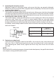
NAME OF PARTS Switch trigger Handle Tail cover Front cover Hexagon socket hd. bolt (M5 x 10) Housing cover Housing Retainer Name plate Side handle Bolt, Spring lock washer (M8 x 30) Fig. 1 NOTE: Install the side handle with the supplied 4 bolts and 4 spring lock washers. Tighten the bolts securely with the supplied wrench. SPECIFICATIONS Motor Power Source Current Full-Load Impact Rate: Weight Single-Phase, Series Commutator Motor Single-Phase, 115V AC, 60 Hz 12.2A 850/min 68.4 lbs (31.
OPTIONAL ACCESSORIES…sold separately 1. Bull point Overall length: 20-15/32”(520 mm) Code No.: 985230 2. Cold chisel Overall length: 20-15/32” (520 mm) Code No.: 985231 3. Scoop Overall length: 21-1/2” (546 mm) Code No.: 985233 4. Cutter Overall length: 20-15/32” (520 mm) Width: 2-15/16” (75 mm) Code No.
NOTE: Use a manual hammer to open/close the retainer as it is too heavy to move by hand. Fig. 2 Fig. 3 NOTE: When removing the accessory, such as a bull point, a cutter etc., follow the above procedure in reverse order. OPERATION 1. 2. Pull the trigger switch after applying the tip of the bit to the crushing position. In some cases, it is necessary to punch the tip of the bit against the crushing position forcibly in order to begin the striking stroke. This is not due to malfunction of the power tool.
2. 3. 4. Inspecting the mounting screws: Regularly inspect all mounting screws and ensure that they are properly tightened. Should any of the screws be loose, retighten them immediately. Failure to do so could result in serious hazard. Inspecting the retainer (Fig.2 and 3) The retainer may become loose due to excessive use. Always, pay attention to its proper functioning to securely hold the accessory shank portion.
9
Item No. 1 2 3 4 5 6 7 8 9 10 11 12 13 14 15 16 17 18 19 20 21 22 23 24 25 26 27 28 29 30 31 32 33 34 35 36 37 38 39 40 41 42 43 44 45 46 47 48 49 50 51 52 53 54 55 56 57 Part Name Roll Pin Lever Pin Bolt Retainer Front Cover O-Ring (S-90) O-Ring Second Hammer O-Ring (D) O-Ring (A) Hammer Holder Hexagon Socket Hd. Bolt Stopper Washer Handle (A) Rubber Leg Cord Clip Tapping Screw Handle Rubber Handle (B) Switch Support Hexagon Socket Hd.
WARNING: Some dust created by power sanding, sawing, grinding, drilling, and other construction activities contains chemicals known to the State of California to cause cancer, birth defects or other reproductive harm. Some examples of these chemicals are: • Lead from lead-based paints, • Crystalline silica from bricks and cement and other masonry products, and • Arsenic and chromium from chemically-treated lumber. Your risk from these exposures varies, depending on how often you do this type of work.