User's_Guide/H_表紙 98.4.8 2:45 PM ページ 1 (1,1) Handheld PC Hardware User's Guide MODEL : HPW-200EC Please read this manual carefully before operating your set. Retain it for future reference. Record model number and serial number of the set. See the label attached on the back cover and quote this information to your dealer when you require service.
Caution for Authority Microsoft, windows, and the Windows logo are either registered trademarks or trademarks of Microsoft Corporation in the United States and/or other countries. Compact Flash is a trademark of SanDisk Corporation in the United States. HITACHI is a trademark of Hitachi ,Ltd. Copyright C1998, Hitachi,Ltd.
Warning Charges or modifications not expressly approved by the party responsible for compliance could void the user's authority to operate the equipment. This equipment has been certified to comply with the limits for a class B computing device, pursuant to FCC rules. In order to maintain compliance with FCC regulations, cables (standard) packed together with this equipment must be used. For VGA display, the unique cable (model:HPW-WVCB) must be used.
6. This product should be operated from the type of power source in dicated on the marking label. If you are not sure of the type of power available, consult your dealer or local power company. 7. Do not locate this product where the cord will be walked on. 8. If an extension cord is used with this product, make sure that the total of the ampere ratings on the products plugged into the extension cord do not exceed the extension cord's ampere rating.
13.Never install telephone jacks in wet locations unless the jack is specifically designed for wet locations. 14.Never touch uninsulated telephone wires or terminals unless the telephone line has been disconnected at the network interface. 15.Use caution when installing or modifying telephone lines. 16.Avoid using this equipment during an electrical storm. There may be a remote risk of electric shock from lightning. 17.Do not use this equipment to report a gas leak in the vicinity of the leak.
The telephone company may make changes in its facilities, equipment, operations, or procedures that could affect the operation of the equipment. If this happens, the telephone company will provide advance notice in order for you to make the necessary modifications in order to maintain uninterrupted service. If trouble is experienced with this equipment HPW-200EC, please contact HITACHI Home Electronics(America), Inc. [ Phone 1 (800) - HITACHI ] for repair and(or) warranty information.
Industry Canada Terminal Equipment Statement "NOTICE : The Industry Canada label identifies certified equipment. This certification means that the equipment meets telecommunications network protective, operational and safety requirements as prescribed in the appropriate Terminal Equipment Technical Requirements document(s). The Department does not guarantee the equipment will operate to the user's satisfaction.
Caution to users Changes or modifications to this product not expressly approved by the party responsible for compliance could void the user's authority to operate the equipment. Caution for Rechargeable Li-ion Battery Pack Please don't reconstruct rechargeable Li-ion battery pack. In rechargeable Liion battery pack, there is safety device and protection device to prevent from damage.
color or shape, don't use this pack and contact sales company. It is possible that generate heat, smoke, damage and ignition. Caution Danger of explosion if battery is incorrectly replaced. Replace only with the same type recommended by the manufacturer. Dispose of used batteries according to the manufacturer's instructions. Attention Il y a danger d'explosion s'il y a remplacement incorrect de la batterie. Remplacer uniquement avec une batterie du m eme type recommande par le constructeur.
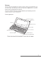
Welcome You can take the Handheld PC just about anywhere. With your Handheld PC, you are free to roam, take documents with you, keep track of appointments, send and receive e-mail, and connect to the Internet. This User's Guide will help you install your batteries and introduce you to the hardware features of your Handheld PC.
Battery Cover Reset Switch Eject Knob (PCMCIA Card) Battery Cover Lock Switch RAM/ROM Memory Cover RAM/ROM Memory Cover Screw Picture from the Bottom of the Handheld PC In addition to the Handheld PC, you should have received the following accessories: Rechargeable Li-ion Battery Pack Handheld PC Serial Cable Handheld PC User's Guide MicrosoftR WindowsR CE The Handheld PC Companion (User's Guide) Stylus Pen CD-ROM with Desktop Software for MicrosoftR WindowsR CE AC adapter Bonus Software CD-ROM MobileSo
Running your Handheld PC Batteries and power You can run your Handheld PC on battery power or with the AC adapter. In addition, the Backup battery provides protection against loss of data. The main battery requires rechargeable Li-ion battery pack. If you run your Handheld PC on main battery while using a high power consumption device such as a PC Card, your battery will drain before long. It is recommended that you use the AC adapter when a PC Card is in use. Backup battery is a rechargeable coin cell.
Operating your Handheld PC with the Main batteries To insert the rechargeable Li-ion battery pack 1 Slide the Main Battery Cover lock switch to the FREE position, then slide the Main Battery Cover in the direction of the arrow. 2 Insert rechargeable Li-ion battery pack into the main battery compartment in the direction indicated as align Battery port. 3 Close the Main Battery Cover and slide the Main Battery Cover lock switch to the LOCK position.
Note Conserving battery power. 1. Don't use battery power for communication. 2. Shorten auto-suspend time. To change the main battery. Main battery is a rechargeable Li-ion battery. It can be recharged about 500 times approximately. If main battery is dead, please replace new one. 1 Slide the battery cover lock switch to the FREE position, then slide the main battery cover in the direction of the arrow. 2 Insert the new battery as described on page 12.
Operating your Handheld PC with the AC adapter. 1 Connect the AC adapter to the Handheld PC, and then plug it into an AC outlet. 2 Make sure the battery cover lock switch to the LOCK position. DC-IN AC Adapter Jack AC Adapter Connection Note The Handheld PC will not operate while the battery cover lock switch is in the FREE position. Charging rechargeable Li-ion battery pack The rechargeable Li-ion battery pack is recharged whenever your Handheld PC receives power from the AC adapter.
charging check LED Caution When you try to recharge a fully charged battery immediately, charging stops to protect the battery. If you use your handheld PC in high temperature environment, charging LED will be illuminated RED color and stop charging automatically. In this case, disconnect AC adapter and after cooling connect AC adapter to charge. Notification LED LED is blinking while Alarm is running.
Using the stylus Pen To use the stylus Pen: Pull and Push the stylus on the right, and use it. Stylus Pen Push/Pull Using the Stylus Pen Wireless infrared transfer Your Handheld PC includes an infrared (IR) port that enables you to transfer files to or from Desktop PC, or another Handheld PC. No special hardware is required for wireless infrared communication. Your Handheld PC must be correctly aligned so their infrared ports face each other and are less than 70cm (27 inches) apart.
IR Port IR Port Data transfer Between Handheld PCs Interface cable Your Handheld PC's SERIAL/VGA connector is located on the left side of the Handheld PC. The serial cable included with your Handheld PC is configured for connection to a desktop computer only. Handheld PC Connector (26Pin Tongue-in-Groove Type) To Desktop Computer PC Serial Port 9 Pin Connector Left Side View of Handheld PC Note : If you want detailed description, please refer to The Handheld PC Companion (WindowsR CE) User's guide.
PC card slot You can use many types of PC cards (also known as PCMCIA cards) with your Handheld PC, including memory cards for saving information, and PC modem cards for communication. A list of compatible PC cards is available in Page 34, "PC card compatibility" . To insert a PC card Insert a PC card in the PC card slot [ figure a)]. To remove a PC card Push the PC Card Eject Knob in the direction of the arrow [ figure b)].
Using the CF card. (also known as Compact Flash card) To insert a CF card 1 Remove the Protection Cover. 2 Insert a CF card in the Compact Flash card slot. 3 Set the Protection Cover. To remove a CF card 1 Remove the Protection Cover. 2 Push the Eject Knob. Pull CF card cover To remove the CF card Note A CF (Compact Flash) card is Memory only. Caution 1 Don't insert the PC/CF card at an angle. 2 Don't insert or remove the PC/CF card during access. 3 Don't power off during the working of PC/CF card.
To use a modem 1. Pull the Phone Jack Cover to open. 2. Insert Fax Modem Phone Cable to analog telephone line. 3. Connect the Fax Modem Phone Cable to the Phone Jack. Note 1 You can update the modem using Software modem diskette which is shipped with the Handheld PC hardware. Please follow the steps: 1.Start Windows 95 or Windows NT on your desktop computer. 2.Connect Handheld PC to the desktop computer with serial cable. 3.Insert the Software Modem diskette in drive A. 4.
RAM/ROM Slot To put additional RAM board 1 Backup all data in your Handheld PC to desktop PC. 2 Remove AC Adaptor and main battery. 3 Push the Backup off Switch(refer "to perform a full reset" ) 4 Wait over 30 seconds. 5 Put off screw and open the RAM/ROM Cover. 6 Put the additional RAM board on RAM connector. 7 Put on the RAM/ROM Cover and screw. 8 Set main battery and AC Adaptor. 9 Push the reset button. 10 After finishing Welcome wizard, restore your data from desktop PC.
To change ROM board If upgrade ROM board released, you can change ROM board to upgrade. Please take the same procedure as "To put additional RAM board " and change ROM board. ROM Connector Caution Backup all data in your Handheld PC to desktop PC before you perform to change ROM board, otherwise all data in your Handheld PC will be erased.
VGA Output Of Pocket PowerPoint Viewer General Description : This manual describes the VGA output of the Handheld PC using Microsoft Pocket PowerPoint Viewer. Pocket PowerPoint enables Handheld PC users to present existing PowerPoint 97 presentations to audiences using either a LCD screen or an external VGA device. Though not as powerful as the desktop client, Pocket PowerPoint Viewer enables Handheld PC users to present simple presentation without lugging a heavy laptop on the road.
4.Click VGA Driver in the menu and follow the instructions. After you have installed VGA driver, connect the monitor cable, select Tools menu in the command bar, select the Set Up Show command, and then choose External VGA in the View Show on list box. In this point LCD output is still active because the Pocket PowerPoint is not in slide show mode.
Even though the LCD display is off while you are making a PowerPint 97 presentation through the VGA cable, the touch panel remains active. Since you can't see where to tap the touch panel, we suggest using the following keys to manipulate your presentation. Press Function Right-arrow, N, Enter, Spacebar Advance to the next slide Left-arrow, P, Backspace Return to the previous slide + Enter Go to slide ESC End a slide show E Erase on-screen annotations 8.
2. Microsoft Pocket PowerPoint Viewer is a simplified or Pocket version of desktop PowerPoint 97. All the functions of the desktop version are not available. For example, animation facilities of the desktop version take no effect in the Pocket PowerPoint Viewer. 3. Pocket PowerPoint Viewer uses a large area of DRAM memory to display VGA output. Therefore, be sure not to adjust program memory size to 3MB or less. Otherwise, your presentation can not be displayed on the VGA screen. 4.
Note 1 Voice Recorder gives the user the ability to capture, organize, and review notes quickly. 2 If you open and close voice recorder application software repeatedly, the system might lock up.
To use Quick Launch Key Invokes the application program assigned to each icon. It provides easy access to frequently used application. :Invokes Microsoft Pocket Word. :Invokes Microsoft Pocket Excel. :Invokes Microsoft Pocket PowerPoint.
To use and key. When you are opening several pocket Word or Pocket Excel windows at the same time, you can use or key in combination with Shift or Ctrl keys as follows: 1.Press (or )alone: Makes next Pocket Word (or Pocket Excel) window to the front. 2.Press Shift + (or ):Makes last Pocket Word (or Pocket Excel) window to the front. 3.Press Ctrl + (or ):Starts a new Pocket Word (or Pocket Excel) window.
Resetting your Handheld PC Occasionally, you may need to reset your Handheld PC to correct software errors of other problems. Performing a simple reset closes all programs that are running and restarts Windows CE. In case the problems are not solved after a simple reset, it is recommended that you perform a manual reset (Press the Power On/Off button, followed by pressing the Reset button about one second and then releasing it, followed by releasing the Power On/Off button.).
Precautions After you start using your Handheld PC, you must maintain a constant supply of power or all stored data will be erased. When you use the AC adapter the main battery lock switch must be in the LOCK position. Use only "HPW - WACA" AC adapter. If your Handheld PC does not operate after you have not used it for a long time, the main battery may have run down. If you believe this is the case, connect the AC adapter.
Weight Weight: about 820g [including Re-chargeable Batteries ] Environmental Tolerance Operating : 41 F to 95 F at 30 80 % humidity Non-operating :-4 F to 140 F at 5 85%humidity Memory 16MB DRAM 12MB ROM Major Applications Microsoft Pocket Word Microsoft Pocket Excel Microsoft Pocket Power Point Viewer Microsoft Voice Recorder Microsoft Pocket Internet Explorer Inbox Calendar Tasks Contacts World Clock Calculator Communication Software Fax/Modem Biz Calc bFax Pro Pocket Finance Accessories Rechargeable
Power Main Battery Li-ion Rechargeable Battery pack AC adapter Input 100 240 V AC Output 10V DC System Voltage 3.3 V Main Source 3.3 V and 5V PC card 3.3 V CF card Peripheral and Transfer Interface Serial Port Data transfer speed (Max 115.2kbps) Infrared Port 70 cm range (depends on the system used) about 30 viewing angle Data transfer speed of 2400bps to 115.2Kbps Ir DA ver1.
PC Card Compatibility Compatible I/O Cards Motorola Modem Card [Montana 33.6] USRobotics SPORTSTER PC Card 33.6 [SP1336] Xircom Modem Card [Credit 28.8] Xircom Modem Card [Credit 33.6] Socket Ethernet [LP-E] Socket [Socket I/O Serial Card] Colorgraphics [Voyager VGA Card] Compatible Memory Cards SanDisk 10MB [SDP3B] SanDisk 20MB [SDP3B] Simple Tech. Flash Memory 4 MB [STI-ATAFL/4] Simple Tech. Flash Memory 8 MB [STI-ATAFL/8] Simple Tech.
1.MODEM SPECIFICATION 1.1.DATA MODEM 1.1.1.Standard V.21 - 300 bps V.22 - 1200bps V.22bis - 2400bps V.32 - adaptive rate 4800 - 9600bps V.32bis - adaptive rate 4800 - 14400kbps V.32terbo - adaptive rate 4800 - 19200kbps V.34 - adaptive rate 2400-33600 bps, including V.8 negotiation 1.1.2.Data Compression V.42bis 1.1.3.Error Correction V.42 LAPM 1.2.FAX MODEM 1.2.1.Compatibility Specification Fax Class 1 1.2.2.Standard V.33 - 14400kbps, 12000bps V.17 - 7200bps including short train V.
2.AT COMMAND SET The AT command set for the modem. The command result code is "always "OK "unless stated otherwise in the command description. A/ - Re-execute Command The A/ command instructs the modem to re-execute the last AT command. It will repeat the command already in the command buffer. This command does not require AT prefix and does not have to be followed by the terminator character. This command is mostly used to redial the last number in case of a busy signal.
Dn - Dial This command instructs the modem to go off-hook and dial the number specified by the dial string supplied as a command parameter. The execution of this command is affected by +FCLASS command settings. If +FCLASS=0 is selected, The modem will try to establish data connection with the remote modem after the dialing is completed. If dial string is empty the modem will try to establish data connection immediately.
Fn - Select Modulation (Compatibility only) This command selects the modulation to be used during data connection. This command is enabled for compatibility only, and using N command and S37 register is the recommended way of selecting the desired modulation. The F command will change the settings of both the N command and the S37 register. F0 Enables automoding. Sets N1, sets S37 to 0. This command instructs the modem to connect at the highest speed supported by both modems.
On - Return to On-Line Data Mode This command is only valid in on-line command mode. If the modem is off-line it will return ERROR result code. O0 This command instructs The modem to go to on-line data mode. O1 This command instructs The modem to go to on-line data mode and initiate a retrain. O2 This command instructs The modem to go to on-line data mode and initiate a rate renegotiation. P - Set Pulse Dialing as a default This command instructs the modem to use pulse dialing as the default dialing method.
Xn - Extended Result Codes Control This command selects which result codes will be used by The modem. X0 Busy detection is disabled, blind dialing (no dial tone detection) is enabled. The following result codes are supported: OK, CONNECT, RING, NO CARRIER, ERROR. X1 Busy detection is disabled, blind dialing (no dial tone detection) is enabled. The following result codes are supported: OK, RING, NO CARRIER, ERROR, CONNECT . X2 Busy detection is disabled, blind dialing is disabled.
Table 3-1.
n - Value in ATXn Command Short Form Long Form 0 1 2 3 4 5 65 CARRIER 33600 Y Y Y Y Y Y 67 COMPRESSION: V.
&Gn - Select Guard Tone This command instructs the modem which if any guard tone should be used for V.22/V.22bis modulation. &G0 Disables guard tone (default) &G1 Selects 500Hz guard tone &G2 Selects 1800 Hz guard tone &Kn - Flow Control This command instructs the modem which flow control method to use.
&V - Display Current Configuration. This command displays the current configuration of the modem. &Wn - Store Current Configuration It stores the current configuration to one of two stored configurations defined by the command parameter. &W0 Store the current configuration as profile 0 &W1 Store the current configuration as profile 1 &Yn - Selects a Default Reset Profile It selects which one of two profiles to load after a reset.
2.1.ERROR DETECTION AND DATA COMPRESSION COMMANDS 2.1.1.AT% Commands %C - Enable/Disable Data Compression Enables or disables data compression negotiation. The modem can only perform data compression on an error-corrected link. %C0 Disables data compression (default) %C2 Enables V.42bis data compression %C3 Enables V.42bis data compression Note that HardModems typically support MNP5 with %C1 and MNP5 or V.42bis with %C3. 2.2.
NO DIALTONE (6) For X2 and X4, the modem sends this result code if it has been instructed to wait for dial tone during dialing but none is received. BUSY (7) For X3 and X4, if busy tone detection is enforced, the modem sends this result code when attempting to originate a call if the busy signal is detected on the line.
CARRIER 24000 (56) CARRIER 26400 (57) CARRIER 28800 (58) CARRIER 31200 (60) CARRIER 33600 (65) The modem sends one of these when the indicated data rate (in bps) has been detected on the line and carrier reporting has been enabled. COMPRESSION: V.42bis (67) COMPRESSION: NONE (69) One of these is sent when the modem has connected in V.42bis and COMPRESSION message reporting has been enabled.
3.S-REGISTERS The S-Registers are summarized in the table below along with their default values; registers may be stored in one of the two user profiles by entering the &Wn command. Register designations can be easily changed by modifying the modem sources. The appropriate AT command which controls the relevant bits in the S-Register should be used to change the value. 3.1.
S2 - Escape Character S2 holds the decimal value of the ASCII character used as the escape character. The default value corresponds to an ASCII '+' . A value over 127 disables the escape process, i.e., no escape character will be recognized. Range: 0-255 Default: 43 (+) S3 - Carriage Return Character Sets the command line and result code terminator character. Pertains to asynchronous operation only.
S11 - DTMF Tone Duration Sets the duration of tones in DTMF dialing. This value has no effect on pulse dialing. Range: 50-255 milliseconds Default: 95 (95 milliseconds) S12 - Escape Guard Time Defines the guard time for the escape sequence, in fiftieths of a second. Range: 0-255 1/50ths of a second Default: 50 (1 second) S36 - LAPM Failure Control This value indicates what should happen upon a LAPM failure.
S38 - Delay Before Forced Hang Up This register specifies the delay between the modem's receipt of the H command to disconnect (or ON-toOFF transition of DTR if the modem is programmed to follow the signal), and the disconnect operation. Applicable to error-correction connection only. This register can be used to ensure that data in The modem buffer is sent before the modem disconnects. 1.
4.FAX CLASS 1 COMMANDS +FCLASS=n - Select Service Class +FCLASS=n command sets the active service class. Parameters: 0-1 Command options: +FCLASS=0 Select Data Mode (default) +FCLASS=1 Select Facsimile Class 1 +F? - Report Active Configuration +F? interrogates the modem to determine the active configuration.
+FRS=n - Receive Silence +FRS=n causes the modem to report back to the DTE with an OK result code after n 10 msintervals of silence have been detected on the line. This command is aborted if any character is received from the DTE. The modem discards the aborting character and issues an OK result code. An ERROR response code results if this command is issued while the modem is on-hook. +FTM=n - Transmit Data +FTM=n causes the modem to transmit data using the modulation defined below.
@@@@@@@@@@@@@@ @@@@@@@@@@@@@@@@@@@@@@@@@@@@@@@@@@@@@@@@@@@@@@@@@@@@@@@@@@@@@@@@@@@@@@@@@@@@@@@@@@@@@@@@@@@@@@@@@@@@@@@@@@@@@@@@@@@@@@@@@@@@@@@@@@@@@@@@@@@@@@@@@@@@@@@@@@@@@@@@@@@@@@@@@@@@@@@@@@@@@@@@@@@@@@@@@@@@@@@@@@@@@@@@@@@@@@@@@@@@@@@@@@@@@@@@@@@@@@@@@@@@@@@@@@@@@@@@@@@@@@@@@@@@@@@@@@@@@@@@@@@@@@@@@@@@@@@@@@@@@@@@@@@@@@@@@@@@@@@@@@@@@@@@@@@@@@@@ @@@@@@@@@@@ @?h@?e @?h@ @?@@@@@@@?@?@@ @@@@@?@@@@@@@?@@@@@@@?@@@@@@@?@@@@@@@?@@@@@@@?@@@@@@@?@@@@@@@?@@@@@@@?@@@@@@@?@@@@@@@?@@@@@@@?@@@@@@@?@@@@@@@?@@@@@@@?@@@
User's_Guide/H_表紙 98.4.8 2:45 PM ページ 1 (1,1) Handheld PC Hardware User's Guide MODEL : HPW-200EC Please read this manual carefully before operating your set. Retain it for future reference. Record model number and serial number of the set. See the label attached on the back cover and quote this information to your dealer when you require service.