INSTALLATION MANUAL MANUAL DE INSTALACIÓN MANUALE DI INSTALLAZIONE NOTICE D'INSTALLATION ROOM AIR CONDITIONER WALL MOUNTED TYPE HSU-09RD03/R2(SDB) HSU-12RD03/R2(SDB) Read this manual before installation Explain sufficiently the operating means to the user according to this manual. NO.
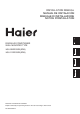
Necessary Tools for Installation 1.Driver 2.Hacksaw 3.Hole core drill 4.Spanner(17,19 and 26mm) 5.Torque wrench(17mm,22mm,26mm) 6.Pipe cutter 7.Flaring tool 8.Knife 9.Nipper 10.Gas leakage detector or soap-and-water solution 11.Measuring tape 12.Reamer Drawing for the installation of indoor and outdoor units The models adopt HFC free refrigerant R410A No.
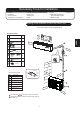
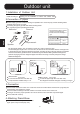
Floor fixing dimensions of the outdoor unit (Unit:mm) )L[LQJ RI RXWGRRU XQLW )L[ WKH XQLW WR FRQFUHWH RU EORFN ZLWK EROWV PP DQG QXWV ILUPO\ DQG KRUL]RQWDOO\ :KHQ ILWWLQJ WKH XQLW WR ZDOO VXUIDFH URRI RU URRIWRS IL[ D VXSSRUWHU VXUHO\ ZLWK QDLOV RU ZLUHV LQ FRQVLGHUDWLRQ RI HDUWKTXDNH DQG VWURQJ ZLQG ,I YLEUDWLRQ PD\ DIIHFW WKH KRXVH IL[ WKH XQLW E\ DWWDFKLQJ D YLEUDWLRQ SURRI PDW ,QGRRU 8QLW 6HOHFWLRQ RI ,QVWDOODWLRQ 3ODFH 3ODFH UREXVW QRW FDXVLQJ YLEUDWLRQ ZKHUH W
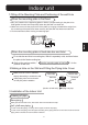
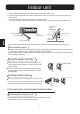
Indoor unit 1.Fitting of the Mounting Plate and Positioning of the wall Hole When the mounting plate is first fixed 1.Carry out, based on the neighboring pillars or lintels, a proper leveling for the plate to be fixed against the wall, then temporarily fasten the plate with one steel nail. 2. Make sure once more the proper level of the plate, by hanging a thread with a weight from the central top of the plate, then fasten securely the plate with the attachment steel nail. 3.
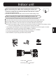
Indoor unit 1. Insert the drain hose into the dent of heat insulation materials of indoor unit. 2. Insert the indoor/outdoor electric cable from backside of indoor unit, and pull it out on the front side, then connect them. 3. Coat the flaring seal face with refrigerant oil and connect pipes.
,QGRRU XQLW :KHQ FRQQHFWLQJ WKH FDEOH DIWHU LQVWDOOLQJ WKH LQGRRU XQLW ,QVHUW IURP RXWVLGH WKH URRP FDEOH LQWR OHIW VLGH RI WKH ZDOO KROH LQ ZKLFK WKH SLSH KDV DOUHDG\ H[LVWHG 3XOO RXW WKH FDEOH RQ WKH IURQW VLGH DQG FRQQHFW WKH FDEOH PDNLQJ D ORRS :KHQ FRQQHFWLQJ WKH FDEOH EHIRUH LQVWDOOLQJ WKH LQGRRU XQLW ,QVHUW WKH FDEOH IURP WKH EDFN VLGH RI WKH XQLW WKHQ SXOO LW RXW RQ WKH IURQW VLGH /RRVHQ WKH VFUHZV DQG LQVHUW WKH FDEOH HQGV IXOO\ LQWR WHUPLQDO EORFN WKHQ WLJKWHQ WKH VFUHZV 3XOO WK
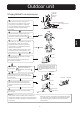
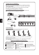
Outdoor unit 1.Installation of Outdoor Unit Install according to Drawing for the installation of indoor and outdoor units 2.Connection of pipes To bend a pipe, give the roundness as large as possible not to crush the pipe ,and the bending radius should be 30 to 40 mm or longer. Connecting the pipe of gas side first makes working easier. The connection pipe is specialized for R410A. Flare nut Half union Forced fastening without careful centering may damage the threads and cause a leakage of gas.
Outdoor unit 2-way valve Liquid Side 5.Purging Method:To use vacuum pump 3-way valve Gas Side 1 Detach the service port's cap of 3-way valve, the Gaugemanifold(for R410A) valve rod's cap for 2-way valve and 3-way's, connect Anti countercurrent joint the service port into the projection of charge hose (Iow) for gaugemanifold. Then connect the projection of charge hose (center) for gaugemanifold into Tube(for R410A) vacuum pump.
1.Power Source Installation The power source must be exclusively used for air conditioner. (Over I0A) In the case of installing an air conditioner in a moist place, please install an earth leakage breaker. For installation in other places, use a circuit breaker as far as possible. 2.Cutting and Flaring Work of Piping Pipe cutting is carried out with a pipe cutter and burs must be removed. After inserting the flare nut, flaring work is carried out. A Flare tool for R410A Flare tooling die 1.
Herramientas necesarias para realizar la instalación 1. Destornillador 5. Llave dinamométrica (17 mm, 22 mm, 26 mm) 6. Cortador de tubo 7. Llave para tuercas cónicas 8. Cuchilla 2. Sierra para metales 3. Taladro 4. Llave (17, 19 y 26 mm) 9. Pinzas 12. Avellanador 10. Detector de fugas de gas o solución de agua jabonosa 11.
297 106.5 566 106.5 Dimensiones de fijación al suelo de la unidad exterior (Unidades: mm) Fijación de la unidad exterior Unidad interior Fije la unidad a un bloque de cemento con pernos (ø10 mm) y tuercas firme y horizontalmente. Si instala la unidad sobre una pared, techo o tejado, instale un soporte con clavos o cables considerando la posibilidad de terremotos o viento fuerte. Si la vibración afectase a la casa, fije la unidad instalando una alfombra de absorción de vibraciones.
Unidad interior 1. Instalar la placa de montaje y ubicar el orificio en la pared Al fijar por primera vez la placa de montaje 1. Nivele correctamente la placa a fijar contra la pared basándose en pilares o dinteles cercanos y fije temporalmente la placa con un clavo de acero. 2. Asegúrese de nuevo de que la placa se encuentre bien nivelada colgando una plomada desde el punto superior central de la placa. Una vez comprobado, fije la placa con el clavo de acero de fijación. 3.
Unidad interior 1. Pase la manguera aislante a través del hueco de los materiales de aislamiento de calor de la unidad interior. 2. Inserte los cables eléctricos de interior / exterior a través de la parte trasera de la unidad interior y tire de ellos desde la parte delantera. Conéctelos entonces. 3. Cubra la cara de sellado cónica con aceite refrigerante y conecte los tubos. Cubra la conexión con material aislante de calor y asegúrese de fijarla con cinta adhesiva.
Unidad interior Al conectar el cable después de instalar la unidad de interior 1. Inserte desde fuera el cable en la sala a través del lado izquierdo del orificio de la pared en el que ya se encuentra el tubo. 2. Tire del cable desde el lado delantero y conecte el cable creando un bucle. Al conectar el cable antes de instalar la unidad de interior Inserte el cable desde la parte trasera de la unidad y tire desde la parte delantera.
Unidad exterior 1. Instalación de la unidad exterior Instale la unidad exterior de acuerdo con el Diagrama de instalación de unidades interiores y exteriores. 2. Conexión de los tubos Para doblar un tubo, intente hacer la curva lo más suave posible para no aplastar el tubo. El radio de doblado debe ser superior a 30 o 40 mm. Será más sencillo conectar en primer lugar el tubo de gas. El tubo de conexión es especial para el tipo R410A.
Unidad exterior Válvula de 2 vías 5. Método de purga: para utilizar una bomba de vacío Lado de líquido Válvula de 3 vías Lado de gas Retire el tapón del puerto de mantenimiento de la válvula de 3 vías (G), el tapón del vástago de la válvula de 2 vías (L) y las 3 vías (G), y conecte el puerto de mantenimiento a la manguera de proyección de carga (inferior) del colector. Conecte entonces la manguera de proyección de carga (central) del colector a la bomba de vacío.
,QVWDODFLyQ GH OD IXHQWH GH DOLPHQWDFLyQ /D IXHQWH GH DOLPHQWDFLyQ GHEH XWLOL]DUVH H[FOXVLYDPHQWH FRQ HO DSDUDWR GH DLUH DFRQGLFLRQDGR 0iV GH $ (Q FDVR GH LQVWDODU HO DLUH DFRQGLFLRQDGR HQ XQ OXJDU K~PHGR LQVWDOH XQ LQWHUUXSWRU GH IXJDV GH PDVD 3DUD UHDOL]DU OD LQVWDODFLyQ HQ RWUR OXJDU XWLOLFH XQ LQWHUUXSWRU GH FLUFXLWR VLWXDGR OR PiV OHMRV SRVLEOH 7UDEDMRV GH FRUWH \ FRQLFLGDG GH ORV WXERV (O FRUWH GHO WXER VH UHDOL]D FRQ XQ FRUWDGRU GH WXERV 'HEHUiQ HOLPLQDUVH ODV UHEDEDV 'HVSXpV GH LQ
Attrezzi necessari per l'installazione 1.Cacciavite 5.Chiave dinamometrica (17mm, 22mm, 26mm) 9.Pinza 12.Alesatore 2.Seghetto a mano 6.Taglia tubi 10.Rilevatore di perdite di gas o 3.Trapano alesatore 7.Flangiatubi soluzione di acqua saponata 4.Chiave fissa (17,19 e 26mm) 8.Coltello 11.Nastro di misurazione Disegno per l'installazione dell'elemento interno e di quello esterno Ć I modelli adottano il refrigerante R410A privo di HFC Accessori Numero di Accessori 1 più di 15 cm N.
297 106.5 566 106.5 Dimensioni per il fissaggio al suolo dell'elemento esterno (Unità: mm) Fissare l'unità al calcestruzzo o al blocco mediante bulloni (Ø10mm) e dadi, in modo saldo e in senso orizzontale. Collegando l'unità alla superficie di una parete, al tetto o sulla sommità di un tetto, fissare in modo sicuro un sostegno mediante chiodi o cavi, tenendo in considerazione possibili scosse sismiche e venti forti.
Componente interno 1.Inserimento della piastra di montaggio e posizionamento del foro sulla parete Quando si fissa prima la piastra di montaggio 1. Basandosi sui pilastri o sulle architravi vicini, effettuare un livellamento corretto, in modo che la piastra possa essere fissata al muro, poi fissare in modo provvisorio la piastra con un chiodo in acciaio. 2.
Componente interno 1. Inserire il tubo di scarico nella tacca presente sui materiali termoisolanti dell'elemento interno. 2. Inserire i cavi elettrici per interni/esterni dal retro dell'elemento interno e tirarli fuori dal lato frontale, poi effettuare il loro collegamento. 3. Ricoprire con uno strato di olio refrigerante la superficie del dispositivo di tenuta svasato e collegare i tubi.
Componente interno Quando si collega il cavo dopo aver inserito l'elemento interno 1. Inserire dall'esterno il cavo destinato alla stanza nel lato sinistro del foro sulla parete, in cui il tubo esisteva già. 2. Estrarre il cavo sul lato anteriore e collegarlo creando un circuito. Quando si collega il cavo prima di aver installato l'elemento interno Inserire il cavo dal retro dell'unità, poi estrarlo sul lato anteriore.
Componente esterno 1.Installazione del componente esterno Procedere all'installazione secondo il Disegno per l'installazione dell'elemento interno e di quello esterno 2.Collegamento dei tubi Per piegare un tubo, conferire la massima rotondità possibile in modo da non danneggiare il tubo, il raggio di curvatura dovrebbe essere di 30-40 mm o maggiore. Collegare prima il tubo del lato del gas rende il lavoro più semplice. Il tubo di connessione è particolarmente adatto per il refrigerante R410A.
Componente esterno Valvola a 2 vie Lato liquido 5.Metodo per eseguire lo spurgo: utilizzare una pompa per il vuoto Valvola a 3 vie lato gas Staccare il tappo della valvola a 3 uscite (G) della porta di servizio, la calotta di protezione dell'asta delle valvole a 2 uscite (L) e (G), collegare la porta di servizio Collettore manometro (per R410A) al Giunzione per evitare il ritorno prolungamento del tubo di scarico (basso) per il manometro.
,QVWDOOD]LRQH GHOOD VRUJHQWH GL DOLPHQWD]LRQH /D VRUJHQWH GL DOLPHQWD]LRQH GHYH HVVHUH XWLOL]]DWD HVFOXVLYDPHQWH SHU LO FRQGL]LRQDWRUH 3L GL $ 6H VL LQVWDOOD XQ FRQGL]LRQDWRUH LQ XQ OXRJR XPLGR LQVWDOODUH XQ LQWHUUXWWRUH GL SHUGLWD GHOOD WHUUD 3HU LQVWDOOD]LRQL LQ DOWUH VHGL XVDUH LO SL SRVVLELOH XQ LQWHUUXWWRUH GL FLUFXLWR 7DJOLR H VYDVDWXUD GHL WXEL ,O WDJOLR GHL WXEL YLHQH HVHJXLWR FRQ XQ WDJOLD WXEL H OH VEDYDWXUH GHYRQR HVVHUH HOLPLQDWH 'RSR DYHU LQVHULWR XQ GDGR VYDVDWR VL HIIH
nécessaires ààl'installation OutilsOutils nécessaires l'installation 1.Tournevis 2. Scie à métaux 3. Perceuse à prélever des carottes 4. Clé (17, 19 et 26mm) 5.Clé dynamométrique (17mm,22mm,26mm) 6. Coupe-tuyau 7. Outil à évaser 9. Pince 12. Alésoir 10. Détecteur de fuite de gaz ou solution d'eau savonneuse 8. Couteau 11.
297 106.5 566 106.5 Dimensions de fixation au sol de l'unité extérieure (Unité: mm) Fixation de l'unité extérieure Unité intérieure Fixez l'unité sur du ciment ou des dalles à l'aide de boulons (ø10mm) et d'écrous, fermement et horizontalement. Lorsque vous montez l'unité sur une surface murale, un toit ou un dessus de toit, fixez un support de façon sûre à l'aide de clous ou de fils, pour prendre en considération un tremblement de terre et un vent violent.
Unité intérieure 1. Monter la plaque de fixation et positionner le trou sur le mur Lors de la première installation de la plaque de fixation 1. Effectuez, en vous basant sur des piliers ou des linteaux voisins, une mise à niveau appropriée pour que la plaque soit fixée contre le mur, puis fixez temporairement la plaque avec un clou en acier. 2.
Unité intérieure 1. Insérez le tuyau de drainage dans le creux du matériau d'isolation de l'unité intérieure. 2. Insérez le câble électrique intérieur/extérieur depuis l'arrière de l'unité intérieure, et tirez-le en face avant, puis connectez-le. 3. Recouvrez la face du joint évasé d'huile de réfrigération et reliez les tubes.
Unité intérieure Lors du branchement du câble après installation de l'unité intérieure 1. Insérez depuis l'extérieur de la pièce vers le côté gauche du trou mural, dans lequel le tuyau existe déjà. 2. Sortez le câble par la face avant et branchez le en faisant une boucle. Lors du branchement du câble avant installation de l'unité intérieure Insérez le câble depuis la face arrière de l'unité, puis tirez-le depuis la face avant.
Unité extérieure 1. Installation de l'unité extérieure Installez selon le Dessin d'installation pour les unités intérieure et extérieure 2. Branchement des tubes Pour plier un tube, donnez un rayon le plus grand possible de façon à ne pas écraser le tube, le rayon de courbure doit être entre 30 et 40, ou plus. Le fait de brancher le tube du côté gaz en premier facilite le travail. Le tube de connexion est spécial pour le R410A.
Unité extérieure Valve 2 voies Côté liquide Valve 3 voies Côté gaz 5. Méthode de purge : Pour utiliser une pompe à vide Détachez le bouchon du port de service du robinet à 3 voies (G), le bouchon de la tige du robinet pour le robinet à 2 voies (L) et à 3 voies (G), branchez le port de service dans la projection du tuyau de charge (bas) pour le collecteur de jauge. Puis connectez la projection du tuyau de charge (centre) pour le collecteur de jauge dans la pompe à vide.
,QVWDOODWLRQ GH OD VRXUFH G DOLPHQWDWLRQ /D VRXUFH G DOLPHQWDWLRQ GRLW VHUYLU H[FOXVLYHPHQW DX FOLPDWLVHXU 3OXV GH $ 'DQV OH FDV GH O LQVWDOODWLRQ G XQ FOLPDWLVHXU GDQV XQ HQGURLW KXPLGH YHXLOOH] LQVWDOOHU XQ LQWHUUXSWHXU GLIIpUHQWLHO 3RXU O LQVWDOODWLRQ GDQV G DXWUHV HQGURLWV XWLOLVH] DXWDQW TXH SRVVLEOH XQ FRXSH FLUFXLW &RXSHU HW pYDVHU OD WX\DXWHULH /D GpFRXSH GHV WXEHV V HIIHFWXH DYHF XQ FRXSH WXEH HW HQ HQOHYDQW OHV EDYXUHV $SUqV LQVHUWLRQ GH O pFURX pYDVp OH WUDYDLO
Haier Industrial Park, No.1 Haier Road, Qingdao, P.R.China IT CONFORMITÀ ALLE DIRETTIVE EUROPEE PER I MODELLI: CE Tutti i prodotti sono conformi alle seguenti normative europee: - Direttiva 73/23/EEC Basso Voltaggio - Direttiva 2006/95/EC Basso Voltaggio - Direttiva 89/336/EEC Compatibilità elettromagnetica - Direttiva 2004/108/EC Compatibilità elettromagnetica ROHS Il prodotto è conforme alla normativa 2002/95/EEC sulla restrizione d’uso di sostanze inquinanti negli apparecchi elettrici ed elettronici.
Haier Industrial Park, No.1 Haier Road, Qingdao, P.R.
Haier Industrial Park, No.1 Haier Road, Qingdao, P.R.China Contains fluorinated greenhouse gases covered by the Kyoto Protocol R410A 1= kg 2= kg 1+2= kg 2 1 F IT B C D E INFORMAZIONI IMPORTANTI SUL REFRIGERANTE UTILIZZATO Questo prodotto contiene gas fluorurati ad effetto serra inclusi nel Protocollo di Kyoto. Non liberare tali gas nell’atmosfera.
Haier Industrial Park, No.1 Haier Road, Qingdao, P.R.China Contains fluorinated greenhouse gases covered by the Kyoto Protocol R410A 1= kg 2= kg 1+2= kg 2 1 F ES A B C D E INFORMACIÓN IMPORTANTE EN RELACIÓN AL REFRIGERANTE UTILIZADO Este producto contiene los gases fluorados de efecto invernadora regulados por el Protocolo de Kioto. No vierta gases a la atmósfera. La etiqueta rellenada debe pegarse cerca de la conexión de carga del producto (p.ej.