OEM Manual Hard Disk Drive Specifications Ultrastar 10K300 – 300/ 147/ 73/ 36 (SCSI Interface) Models Models Models Models Models Models Models Models HUS103030FL3600 :(300GB/68pin) HUS103014FL3600 :(147GB/68pin) HUS103073FL3600 :( 73GB/68pin) HUS103036FL3600 :( 36GB/68pin) HUS103030FL3800 :(300GB/80pin) HUS103014FL3800 :(147GB/80pin) HUS103073FL3800 :( 73GB/80pin) HUS103036FL3800 :( 36GB/80pin) Read and follow all instructions and cautions for safety described in this document before using the drive.
REVISION CONTROL Remarks Rev.
To use this product safely Read and follow all instructions and cautions described in this chapter before using the drive. It is recommended that this manual is kept at a proper location for quick reference. The description related to safety in this chapter may be changed without notice. Influence for environment Although this product emits electro-magnetic field, it will be found to be in compliance with the EMI regulations such as VCCI class B, FCC Part 15 class B.
To use this product safely (Continued) Followings are the cautions and contents described in this manual. Caution : Items of indicating - Safety cautions for this product Items of indicating Caution : - Safety cautions for this product - Spindle Start and Stop - Mounting of the drive - Reliability temperature - Precautions for handling Page 4 Page 4-5 Page 16 Page 24 Page 26 Page 27 Safety cautions for this product Caution 0.2.1 0.2.2 0.2.3 0.2.
To use this product safely (Continued) Caution 0.2.11 Protect the drive against shocks with the corrugated board and cushioning material provided by the manufacturer, or with Hitachi Approved containers. 0.2.12 When mounting the drive, use the size of screws and the torque recommended in this manual. If non-recommended size of screws and torque are used, it may cause catastrophic failures. 0.2.13 Do not press top cover and bottom PCB of the drive. It may cause catastrophic failures. 0.2.
TABLE OF CONTENTS Chapter Page 1 To use this product safely. ...................................................................... 3 Features................................................................................................... 8 2 Standards and Related Documents ......................................................... 9 3 Description............................................................................................... 10 3.1 3.2 4 Characteristics ...........................
11 Pin assignment ........................................................................................ 33 11.1 SCSI Bus Connector C1 ............................................................. 33 11.2 Other connectors ........................................................................ 37 12 Jumper Socket setting ............................................................................. 38 12.1 Jumper connector layout............................................................. 38 12.
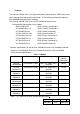
1 Features The Ultrastar 10K300 series uses high performance sputtered disks, GMR heads, and a rotary type voice coil motor to drive the heads. These features provide high capacity, high speed positioning and high reliability. The Ultrastar 10K300 series uses a SCSI interface for data transfer. Related ANSI Specifications are as follows. ANSI X3.
2 Standards and Related Documents (a) Safety standards It is the user’s responsibility to assure the actual system in which the drive is installed meets the appropriate safety requirements. However, the drive was tested to be in compliance with the following standards: UL 60950 3rd Edition CAN/ CSA-C22.2 No.
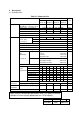
3 Description 3.1 Characteristics Table 3.
3.2 Environmental conditions and reliability Table 3.2 Environmental conditions and reliability Item Environmental conditions Ultrastar Ultrastar 10K300-300 10K300-147 -40 to 70°C Temperature non-operating -40 to 70°C storage/shipping Humidity operating 5 to 90%RH 5 to 90%RH 29°C maximum (non condensing) No corrosive gas, saline atmosphere or organic-metal compound (Example.
Note 1. Note 2. Storage capacity does not include spare sector and spare cylinder. This is the value in the case that the drive is formatted to 512 Bytes/sector. (1 gigabyte shows 1x109 bytes on this document.) Note 3. Ultrastar 10K300 is formatted to 512 Bytes/sector as the default. If non-512 Bytes/sector is required, customer can change it by re-format of the drive. Note 4. Data transfer rate is degraded with cable or host condition or electrical noise. Note 5.
Note 7. The disk drive orientation for shock test is shown in Figure 4.2. Figure 3.2 Shock test direction Test conditions on shock test are as follows. (1) Operating 147m/s2(15G) (Shock mode: half sine wave 11 ms, Test cycle: 5 times) (2) Non-operating 735m/s2(75G) (Shock mode: half sine wave 11 ms, Test cycle: 5 times) 2450m/s2(250G) (Shock mode: half sine wave 2 ms, Test cycle: 5 times) Note 8. Acoustic noise is measured except for the start, stop and seek operations. Note 9.
Note 13. When the Ultrastar 10K300-300 is formatted to 512 Bytes/sector, the maximum Logical Block Address is (22ECB25B)h. When the Ultrastar 10K300-147 is formatted to 512 Bytes/sector, the maximum Logical Block Address is (111D69B4)h. When the Ultrastar 10K300-73 is formatted to 512 Bytes/sector, the maximum Logical Block Address is (88BB9D4)h. When the Ultrastar 10K300-36 is formatted to 512 Bytes/sector, the maximum Logical Block Address is (445DCE9)h. Note 14.
4 DC power Interface 4.1 DC Power Requirement The drives are operated on DC power (+5V, +12V) only. No power sequencing is required. The +5 and +12 Volts can be applied in any order. Table 4.1 DC Power Requirement Power supply Voltage tolerance +5V DC 5.0V +/-5% Allowed ripple and noise Less than 150mVp-p (0 - 100kHz) Less than 100mVp-p (100kHz - 10MHz) +12V DC 12.0V +/-5% Less than 150mVp-p (0 - 100kHz) Less than 100mVp-p (100kHz - 10MHz) Note 1.
4.2 Power supply current +12V Current [A] 3.0 2.0 1.0 0 0 10 T0 T1 T0-T1: Power up T1-T2: Spin-up T2-T3: Servo initialize T3-T4: Upload Code etc T1-T4: Start up 20 Time[S] T2 T3 T0: Power on T1: Accept start unit command or Auto Spin-up T2: Ready Fig 4.1 Current transition for +12V Note: A retry Spin-up operation may be attempted during the Start up process. 4.3 Spindle Start and Stop 4.3.1 Start and Stop Time Table 4.
4.3.2 Spindle Start Selection When multiple disk drives are connected to the same power supply and turned on simultaneously, a large current will be required at power up. In the above case, it is recommended to turn the motors on one by one at intervals in order to minimize 12V line current. This can be done according to the following 3 jumper pin configurations in the case of NW drive: 1.
5 Connecting Methods 5.1 Interface Cable (Daisy Chain) Terminator SCSI interface cable Terminator SCSI bus Ultrastar Ultrastar Ultrastar 10K300 10K300 10K300 DC power power supply cable GND Figure 5.1 Cabling layout (WIDE LVD drive) Note 1. The SCSI bus can accommodate a maximum of 16 units on a WIDE (16-bit) bus, including the host processor, Ultrastar 10K300 units, and other SCSI devices. Note 2.
5.2 Low voltage differential (LVD) mode The NW and NC drives have two different transceivers to allow customer to use it in traditional systems which may use single-ended drivers and receivers, or to use it in low voltage differential (LVD) systems which use LVD drivers and receivers. Their I/O circuits are selectable using the I/O "DIFFSENS" line. When the I/O "DIFFSENS" line is between -0.35V and +0.5V, the drive interface circuits operate single-ended. When "DIFFSENS" is between +0.7V and +1.
6 SCSI Interface 6.1 Summary of SCSI Controller The Ultrastar 10K300 SCSI controller interfaces between the drive and the host computer with the Small Computer System Interface (SCSI). (1) ANSI standard The controller supports the SCSI interface that conforms to the ANSI specifications shown in section 2. (2) Compact design The controller is embedded within the disk drive.
(8) Tagged Command Queuing A maximum of 128 commands can be enqueued to this drive. The drive does not have to connect and disconnect to the host controller even if the SCSI command has been issued successively, so the overhead time of the SCSI bus can be reduced. (9) S.M.A.R.T. (Self - Monitoring, Analysis and Reporting Technology) This function helps predict a failure related to the degradation of the disk drive itself. For users seeking to use the drive as long as possible, S.M.A.R.T.
6.2 Summary of SCSI Commands The SCSI controller supports the group 0,1, and 2 commands listed in Table 6.1 Table 6.
Table 6.1 SCSI Commands Supported (Continued) Operation Code 41h 4Ch 4Dh 55h 56h 57h 5Ah 5Eh 5Fh Operation Code B7h A0h Group 2 Command Name WRITE SAME LOG SELECT LOG SENSE MODE SELECT (10) RESERVE (10) RELEASE (10) MODE SENSE (10) PERSISTENT RESERVE IN PERSISTENT RESERVE OUT Group 5 Command Name READ DEFECT DATA (12) REPORT LUNS 7 Mounting and Handling 7.1 Orientations The following orientations are acceptable. Horizontal (1) Vertical (1) Vertical (3) Horizontal (2) Vertical (2) Vertical (4) Fig.
Caution 7.2 Mounting of the drive 1. Mount the drive with four 6-32 UNC screws. (Screw's torque : 0.588 to 0.784 N·m) 2. Mounting holes (A1,A2,B1,B2,B3) are available for mounting.(See figure 8.3) It is recommended that the 4 holes, (A1,A2 or B1,B3 on figure 8.3), be used for mounting to keep the proper space between mounting holes. 3. Maximum penetration of the screw is 3.8 mm. 4. Keep a clearance of 3 millimeters from the PCB parts side and the HDA's upper surface for proper cooling air ventilation.
7.3 Mounting dimensions F G H J K L B A C D E Dimension A B C D E F G H J K L mm 101.6±0.25 95.25±0.25 3.18±0.25 41.28±0.5 44.45±0.25 147 max. 101.6±0.25 28.5±0.5 41.6±0.25 26.1 max. 6.35±0.25 Figure 7.3 Layout of Mounting holes Drawing No. Sheet No.
7.4 Precautions on the off-line test or bench test When the off-line test or bench test is performed the drive should be tightly fixed and cooled. The set-up should be similar to the actual system configuration. 7.5 Cooling of the drive Keep the drive (HDA and PCB) cool by using a FAN. Reliability and life of the drive increases as the temperature is lower. Caution 7.6 Reliability temperature The temperature measurement points and temperature limits are shown below. 1.
Caution 8 Precautions for handling The drive is sensitive to shock, vibration, over voltage, temperature, humidity, corrosive gas, magnetic force and electrostatic discharge. If these forces contact the electrical or mechanical components (magnetic heads, magnetic disks), the drive will break down, degrade, or storage data will be lost. The following handling guidelines are mandatory.
8.4 Other Precautions 8.4.1 Do not loosen the screws or disassemble the drive. 8.4.2 Do not remove the PCB from the drive or swap the PCB with other drives. 8.4.3 Do not solder the wire or other parts on the PCB, or reconstruct the PCB. 8.4.4 Do not remove the sealing tape or label on the HDA. 8.4.5 Turn off the power before removing or installing the DC power cable and SCSI interface cable. Turn off the power before removing or installing the jumper. 8.4.
10 Physical interface 10.1 Connector Specifications Use the mating connectors which are electrically and mechanically compatible. The following part numbers indicate the mating connectors. Table 10.1 Interface connectors Interface WIDE LVD SCA-2 LVD Name Part number Manufacturer SCSI interface connector 786090-7 DHJ-PAC68-2AN AMP DDK DC power connector Pin:61314-4 Housing:1-480424-0 AMP AMP SCSI interface connector 787311-1 with DC power connector 787565-1 HD2-PA080-S11 AMP AMP DDK 10.
(2) DC Power Supply Cable The DC power cable should be as short as possible to minimize voltage drop. Table 10.2 Interface cable (WIDE, Single-ended mode) Cable Type SCSI interface Flat Ribbon or Twisted Pair DC power supply AWG#20 Maximum cable length Fast-5 Fast-10 6m (16 units max.) 3m (16 units max.) Ultra (Fast 20) 3m (4 units max.) or 1.5m (8 units max.) 3m Table 10.
10.3 Connector Layout WIDE LVD drive SCSI Bus Connector C1 Auxiliary Connector C4 Power Connector C2 Figure 10.1 Connector Layout (WIDE LVD drive) C2-1 : 12V C2-2 : GND (12V Return) C2-3 : GND (5V Return) C2-4 : 5V 34 68 C1 1 11 35 12 C4 C2 1 2 4 3 2 1 Figure 10.2 Connector view Note: The SCSI ID setting is to be set via the C3 connector (not by C4) normally.
SCA-2 LVD drive NP D H M W L Dimension mm Dimension mm H 26.1 max. W 101.6±0.25 D 6.35±0.25 L (58) N (7) M 50.8±0.5 P 4.6±0.5 Figure 10.3 Connector Layout (SCA-2 LVD drive) 41 C1 80 PCB parts side 1 40 Figure 10.4 Connector view Drawing No. Sheet No.
11 Pin assignment 11.1 SCSI Bus Connector C1 Table 11.1 Pin assignment of SCSI Bus Connector C1 (WIDE, Single-ended mode) Signal Name Connector Cable Connector Signal Name contact conductor contact No. No. No.
Table 11.2 Pin assignment of SCSI Bus Connector C1 (WIDE, LVD mode) Signal Name Connector contact No. +DB(12) 1 +DB(13) 2 +DB(14) 3 +DB(15) 4 +DB(P1) 5 +DB(0) 6 +DB(1) 7 +DB(2) 8 +DB(3) 9 +DB(4) 10 +DB(5) 11 +DB(6) 12 +DB(7) 13 +DB(P0) 14 GND 15 DIFFSENS 16 TERMPWR 17 TERMPWR 18 Reserved 19 GND 20 +ATN 21 GND 22 +BSY 23 +ACK 24 +RST 25 +MSG 26 +SEL 27 +C/D 28 +REQ 29 +I/O 30 +DB(8) 31 +DB(9) 32 +DB(10) 33 +DB(11) 34 Cable conductor No.
Table 11.3 Pin assignment of SCSI Bus Connector C1 (SCA-2, Single-ended mode) Signal Name 12V 12V 12V 12V Open Open -DB(11) -DB(10) -DB(9) -DB(8) -I/O -REQ -C/D -SEL -MSG -RST -ACK -BSY -ATN -DB(P0) -DB(7) -DB(6) -DB(5) -DB(4) -DB(3) -DB(2) -DB(1) -DB(0) -DB(P1) -DB(15) -DB(14) -DB(13) -DB(12) 5V 5V 5V Reserved AUTO START (Note 1) -ID0 (Note 1) -ID2 (Note 1) Connector contact No.
Table 11.4 Pin assignment of SCSI Bus Connector C1 (SCA-2, LVD mode) Signal Name 12V 12V 12V 12V Open Open -DB(11) -DB(10) -DB(9) -DB(8) -I/O -REQ -C/D -SEL -MSG -RST -ACK -BSY -ATN -DB(P0) -DB(7) -DB(6) -DB(5) -DB(4) -DB(3) -DB(2) -DB(1) -DB(0) -DB(P1) -DB(15) -DB(14) -DB(13) -DB(12) 5V 5V 5V Reserved AUTO START (Note 1) -ID0 (Note 1) -ID2 (Note 1) Connector contact No.
11.2 Other connectors Table 11.5 Pin assignment of Auxiliary Connector C4 (WIDE LVD drive) Pin No. 1 3 5 7 9 11 Signal Name -ID0 -ID1 -ID2 -ID3 N.C. 5V Pin No. 2 4 6 8 10 12 Signal Name Reserved Reserved Reserved LED(with 150 ohm) GND -WRITE PROTECT Note See Figure 12.1 Table 11.6 Pin assignment of Option Jumper Connector C3 (WIDE LVD drive) Pin No. Signal Name Pin No.
12 Jumper Socket setting 12.1 Jumper connector layout WIDE LVD drive Option Jumper Connector (C3) Force Single-Ended bus mode (11) Disable Auto Start (9) ID0 (7) ID1 (5) ID2 (3) ID3 (1) Enable Delayed Start (13) Write Protect (15) Reserved (17) Reserved (19) LED(with 0ohm) (21) Term. Power to SCSI Bus (23,24) 1 2 23 24 GND (2,4,6,8,10,12,14,16,18,20) 5V(with 150ohm) (22) Auxiliary Connector (C4) Reserved (2) Reserved (4) Reserved (6) 12 11 2 1 LED (8) GND (10) Write Protect (12) 5V (11) N.C.
12.2 Jumper socket setting The Jumper sockets should be set only when the power is off. 12.2.1 SCSI ID WIDE LVD Option Jumper Connector (C3) No.
12.2.2 Disable Auto Start WIDE LVD No. Option Jumper Connector (C3) Meaning 1 Remove the Jumper Socket for C3-9,10 (Default) Spindle motor automatically starts when the power is applied or in sequence via ID number x 10 seconds from the time power is applied if C3-13,14 is jumpered. 2 1 9 23 2 10 24 Install the Jumper Socket for C3-9,10 1 9 23 2 10 Spindle motor starts only by SCSI command 24 12.2.3 Force Single-Ended bus mode WIDE LVD No.
12.2.4 Enable Delayed Start WIDE LVD No. 1 Option Jumper Connector (C3) Spindle motor automatically starts when the power is on. Remove the Jumper Socket for C3-13,14 (Default) 1 13 23 2 2 Meaning 14 24 Spindle motor starts in sequence via ID number x 10 seconds from the time power is applied (NOTE 1) Install the Jumper Socket for C3-13,14 1 13 23 2 14 24 Note 1. This time is as follows: ID number 0 to 7 : ID number x 10sec ID number 8 to 15 : (ID number - 8) x 10sec Note 2.
12.2.5 SCSI bus Terminator Power WIDE LVD No. 1 Option Jumper Connector (C3) Remove the Jumper Socket for C3-23,24 (Default) 23 1 2 2 Meaning Terminator power not supplied to SCSI TERMPWR line 24 Install the Jumper Socket for C3-23,24 1 23 Terminator power supplied to SCSI TERMPWR line (To SCSI bus cable) 24 2 Note 1. In the case that terminator power is supplied to SCSI cable (TERMPWR), precautions must be taken to prevent coupling of the SCSI bus signal. 12.2.6 Write Protect WIDE LVD No.
12.3 Jumper socket part number Part numbers of jumper sockets are as follows: Table 12.1 Jumper socket Connector Name Option Jumper Connector (C3) MINITEK JUMPER Part number 86730-001 Manufacturer FCI Japan K.K. 12.4 Extension connector Part numbers of extension connectors for remote cable are as follows: Table 12.