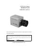
3-CCD Color Camera MODEL HV-D30 OPERATION MANUAL Please read this operation manual carefully for proper operation, and keep it for future reference. Note: The model and serial numbers of your product are important for you to keep for your convenience and protection. the product. These numbers appear on the nameplate located on the bottom of Please record these numbers in the spaces provided below, and retain this manual for future reference. Model No. Serial No. Hitachi Kokusai Electric Inc.
IMPORTANT SAFETY INSTRUCTIONS 1. Read Instructions All the safety and operating instructions should be read before the product is operated. 2. Retain Instructions The safety and operating instructions should be retained for future reference. 3. Heed Warnings All warnings on the product and the operating instructions should be adhered to. 4. Follow Instructions All operating and use instructions should be followed. 5. Cleaning Unplug this product from the wall outlet before cleaning.
11. Power Sources This product should be operated only from the type of power source indicated on the marking label. If you are not sure of the type of power supply to your home, consult your product dealer or local power company. For products intended to operate from battery power, or other sources, refer to the operating instructions. 12. Grounding or Polarization This product is equipped with a three-wire grounding-type plug a plug having a third (grounding) pin.
20. Damage Requiring Service Unplug this product from the wall outlet and refer servicing to qualified service personnel under the following conditions: a. When the power-supply cord or plug is damaged. b. if liquid has been spilled, or objects have fallen into the product. c. If the product has been exposed to rain or water. d. If the product does not operate normally by following the operating instructions.
WICHTIGE SICHERHEITSANWEISUNGEN 1. Alle Anweisungen lesen. Vor Betrieb des Erzeugnisses sollten alle Sicherheits-und Bedienungsanleitungen gelesen werden. 2. Die Anweisungen aufbewahren. Die Sicherheits-und Bedienungsanleitungen sollten fünftigen Bezug aufbewahrt werden. 3. Warnungen beachten. Die Warnungen auf dem Erzeugnis und in den Bedienungsanleitungen solten beachtet werden. 4. Anweisungen befolgen. Alle Bedienungsanleitung-und Verwendungsanweisungen sollten befolgt werden. 5.
10. Ventilation Schlitze und Öffnungen im Gehäuse dienen der Ventilation. Sie sind für zuverlässigen Betrieb des Gerätes und Schutz vor Überhitzung erforderlich und dürfen nicht blockiert oder abgedeckt werden. Die Öffnungen sollten niemals dadurch blockiert werden, daß, das Gerät auf ein Bett, ein Sofa, einen Teppich oder eine ähnliche Oberfläche gestellt wird.
18. Starke stöße oder Vibrationen Setzen Sie das Erzeugnis beim Transport nicht starken Stößen oder Vibrationen aus. 19. Wartung Versuchen Sie nicht, dieses Erzeugnis Selbst zu warten, da Sie sich durch Öffnen bzw. Entfernen von Abdeckungen hohen Spannungen und sonstigen Gefährdungen ausserzen können. Beziehen Sie sich für jegliche Wartung auf qualifiziertes Wartungspersonal. 20.
MISES EN GARDE IMPORTANTES 1. Lire les instructions Lire toutes les instructions de sécurité et de fonctionnement avant de faire fonctionner l’appareil. 2. Conserver ces instructions Conserver les instructions de sécurité et de fonctionnement á des fins de référence ultérieure. 3. Tenir compte des avertissements Tous les avertissements qui figurent sur l’appareil et dans le mode d’emploi devront être respectés. 4. Observer les instructions Observer toutes les instructions de fonctionnement et d’utilisation.
10. Ventilation Les fentes et les ouvertures du coffret sont prévues pour la ventilation ainsi que pour garantir un fonctionnement en toute sécurité de l’appareil et le protéger de toute surchauffe, et ces ouvertures ne devront donc être ni obstruées ni recouvertes. Ne jamais obstruer les ouvertures en placant l’appareil sur un lit, un sofa, un tapis ou toute surface similaire.
18. Chocs ou vibrations violents Lorsqu’on transporte l’appareil, ne pas le soumettre á des chocs ou des vibrations violents. 19. Réparations Ne pas tenter de réparer l’aapareil soi-même car le fait d’ouvrir ou de retirer les caches risque d’exposer l’utilisateur á des tensions dangereuses notamment. Confier toute réparation á un personnel qualifié. 20.
IMPORTANT NOTICE For USA These products have been tested and found to comply with the limits for a Class A digital device, pursuant to Part 15 of the FCC Rules. These limits are designed to provide reasonable protection against harmful interference when the equipment is operated in a commercial environment. This equipment generates, uses, and can radiate radio frequency energy and, if not installed and used in accordance with the instruction manual, may cause harmful interference to radio communications.
Table of contents z IMPORTANT SAFETY INSTRUCTUIONS 㨯㨯㨯㨯㨯㨯㨯㨯㨯㨯㨯㨯㨯㨯㨯㨯㨯㨯㨯㨯㨯㨯㨯㨯㨯㨯㨯㨯㨯㨯㨯㨯㨯 A z IMPORTANT NOTICE 㨯㨯㨯㨯㨯㨯㨯㨯㨯㨯㨯㨯㨯㨯㨯㨯㨯㨯㨯㨯㨯㨯㨯㨯㨯㨯㨯㨯㨯㨯㨯㨯㨯㨯㨯㨯㨯㨯㨯㨯㨯㨯㨯㨯㨯㨯㨯㨯㨯㨯㨯 J z Table of contents 㨯㨯㨯㨯㨯㨯㨯㨯㨯㨯㨯㨯㨯㨯㨯㨯㨯㨯㨯㨯㨯㨯㨯㨯㨯㨯㨯㨯㨯㨯㨯㨯㨯㨯㨯㨯㨯㨯㨯㨯㨯㨯㨯㨯㨯㨯㨯㨯㨯㨯㨯㨯㨯㨯㨯㨯㨯 K z Standard composition 㨯㨯㨯㨯㨯㨯㨯㨯㨯㨯㨯㨯㨯㨯㨯㨯㨯㨯㨯㨯㨯㨯㨯㨯㨯㨯㨯㨯㨯㨯㨯㨯㨯㨯㨯㨯㨯㨯㨯㨯㨯㨯㨯㨯㨯㨯㨯㨯㨯㨯㨯 1 z Overview 㨯㨯㨯㨯㨯㨯㨯㨯㨯㨯㨯㨯㨯㨯㨯㨯㨯㨯㨯㨯㨯㨯㨯㨯㨯㨯㨯㨯㨯㨯㨯㨯㨯㨯㨯㨯㨯㨯㨯㨯㨯㨯㨯㨯㨯㨯㨯㨯㨯㨯㨯㨯㨯㨯㨯㨯㨯㨯㨯㨯㨯㨯㨯 1 z Features 㨯㨯㨯㨯㨯㨯㨯㨯㨯㨯㨯㨯㨯㨯㨯㨯㨯㨯㨯㨯㨯㨯㨯㨯㨯㨯㨯㨯㨯㨯㨯㨯㨯㨯㨯㨯㨯㨯㨯㨯㨯㨯㨯㨯㨯㨯㨯㨯㨯㨯㨯㨯㨯㨯㨯㨯㨯㨯㨯㨯㨯㨯㨯 1 z Notes to users 㨯㨯㨯㨯㨯㨯㨯㨯㨯㨯㨯㨯㨯㨯㨯㨯㨯
z How to Attain Better images 㨯㨯㨯㨯㨯㨯㨯㨯㨯㨯㨯㨯㨯㨯㨯㨯㨯㨯㨯㨯㨯㨯㨯㨯㨯㨯㨯㨯㨯㨯㨯㨯㨯㨯㨯㨯㨯㨯㨯㨯㨯㨯㨯㨯㨯 33 Black Balance Adjustment 㨯㨯㨯㨯㨯㨯㨯㨯㨯㨯㨯㨯㨯㨯㨯㨯㨯㨯㨯㨯㨯㨯㨯㨯㨯㨯㨯㨯㨯㨯㨯㨯㨯㨯㨯㨯㨯㨯㨯㨯㨯㨯㨯㨯㨯 33 White Balance Adjustment 㨯㨯㨯㨯㨯㨯㨯㨯㨯㨯㨯㨯㨯㨯㨯㨯㨯㨯㨯㨯㨯㨯㨯㨯㨯㨯㨯㨯㨯㨯㨯㨯㨯㨯㨯㨯㨯㨯㨯㨯㨯㨯㨯㨯 34 Real time Auto White 㨯㨯㨯㨯㨯㨯㨯㨯㨯㨯㨯㨯㨯㨯㨯㨯㨯㨯㨯㨯㨯㨯㨯㨯㨯㨯㨯㨯㨯㨯㨯㨯㨯㨯㨯㨯㨯㨯㨯㨯㨯㨯㨯㨯㨯㨯㨯㨯㨯 Auto Shading Correction 㨯㨯㨯㨯㨯㨯㨯㨯㨯㨯㨯㨯㨯㨯㨯㨯㨯㨯㨯㨯㨯㨯㨯㨯㨯㨯㨯㨯㨯㨯㨯㨯㨯㨯㨯㨯㨯㨯㨯㨯㨯㨯㨯㨯㨯㨯 ALC (Auto level control) 㨯㨯㨯㨯㨯㨯㨯㨯㨯㨯㨯㨯㨯㨯㨯㨯㨯㨯㨯㨯㨯㨯㨯㨯㨯㨯㨯㨯㨯㨯㨯㨯㨯㨯㨯㨯㨯㨯㨯㨯㨯㨯㨯㨯㨯㨯 Long-Time Store Mode 㨯㨯㨯㨯㨯㨯㨯㨯㨯㨯㨯㨯㨯㨯㨯㨯㨯㨯㨯㨯㨯㨯㨯㨯㨯㨯㨯㨯㨯㨯㨯㨯㨯㨯㨯㨯㨯㨯㨯㨯㨯㨯㨯㨯㨯㨯㨯㨯 z
Standard composition Check when unpacking. Camera, HV-D30 㨯㨯㨯㨯㨯㨯㨯㨯㨯㨯㨯㨯㨯㨯㨯㨯㨯㨯㨯㨯㨯㨯㨯㨯㨯㨯㨯㨯㨯㨯㨯㨯㨯㨯㨯㨯㨯㨯㨯㨯㨯㨯㨯㨯㨯 1 Power plug, R03-P3F (JPR0034*) 㨯㨯㨯㨯㨯㨯㨯㨯㨯㨯㨯㨯㨯㨯㨯㨯㨯㨯㨯㨯㨯㨯㨯㨯㨯㨯㨯㨯㨯㨯 1 Operation Manual㨯㨯㨯㨯㨯㨯㨯㨯㨯㨯㨯㨯㨯㨯㨯㨯㨯㨯㨯㨯㨯㨯㨯㨯㨯㨯㨯㨯㨯㨯㨯㨯㨯㨯㨯㨯㨯㨯㨯㨯㨯㨯㨯㨯 1 * Part code Overview The HV-D30 is a three CCD color camera combining high picture quality and high stability with the convenience of C mount optics. CCD size is 1/3-inch and each is comprised of 410,000 picture elements (470,000 in the PAL version).
Clear low noise images are obtained even in high gain mode. x Auto shading compensation (ASC) Color shading incurred when using a C mount lens is automatically compensated (attenuated). Two modes of shading are provided and can be selected according to the cameras application, a vertical color shading mode or a two-dimensional luminance-shading mode.
z Installation and storage sites The following types of environment can impair performance, lead to damage, pose safety hazards and shorten the useful life of the camera. Select the sites for installing the storing the camera carefully.
3) Moire Interaction between patterns can produce an additional "phantom" pattern to appear. The CCD picture elements (pixels) are arranged in a pattern, which can interact with a pattern in the scene (e.g., a performer wearing a finely striped necktie) to result in a Moire pattern. The effect should be considered when selecting costumes, props and other scene elements. 4) Ghosting Strong direct or reflected light near an object of interest can cause ghosting of the object to appear in the picture.
Name and function each section AWB/L button DERECT mode: Holding down this button for more than two seconds carries out auto white balance (AWB). MENU button Press this button to display the camera setup menu. The switches U, D, L and R provide different functions depending on whether the menu is displayed (MENU mode) or not (DERECT mode). MENU mode: In this mode, it is allowed to change functional data or carry out each function.
Lens CAUTION: Observe the dimensions of the lens mounting selection as illustrated at the left. If the dimensions are not observed, do not use such a lens, because the lens and the camera will be damaged. Flang surface of lens 4.3mm or less Lens selection 1) Optical characteristics The proper lens is vital for obtaining full performance from the camera. The exit pupil distance is particularly important for a 3 CCD type camera. If too short, vertical color shading can appear in the picture.
3) Flangeback adjustment If focus cannot be adjusted after replacing the lens or at the telephoto and wide angle extremes of a zoom lens, the flangeback can be adjusted. Open the lens iris and adjust as described below. x Fixed focus lens Set the lens focus ring to infinity and pickup an image more than 20 meters distant. While observing the picture, adjust the focus by turning the flangeback ring in the F or N direction.
2) Adjustment Hold the U button depressed and press Setup for about 2 seconds to display the Special Set menu. Change to the Lens screen and check the Lens Type setting. If DC, change this to Video. عENS LENS TYPE :VIDEO IRIS GAIN : 0 REFERENCE L 㪭㫀㪻㪼㫆㩷㫃㪼㫍㪼㫃㩷㫀㫅㪻㫀㪺㪸㫋㫆㫉 H (1) Set the lens ALC control fully toward the average (Av ) position. (2) If auto iris hunting occurs, reduce the Iris Gain setting.
Camera mounting The camera is provided with threaded screw holes at the top and bottom. mounting to either a tripod or a mounting bracket. These allow Screw type U 1/4-20 Length: 4.5 to 6 mm 㧸 Screws longer than 6 mm can cause internal damage, while less than 5 mm prevents secure fastening and risks dropping to cause damage and injury.
10 Microscope Rem ote Lens Lens TV Conferencing/Surv eillance Max 8 cam era (Supplied by PAN/TILT system m aker) 㪮㩷㩷㪫 PAN/TILT & Lens Controller *Alev el conv erter is required if controlling the camera from a personal com puter v ia RS-232C intergace ov er a distance m ore than 15 m eter.
Menu Screen Operation 1. Menu Structure For settings in the camera, the MAIN and SPECIAL menus are available. 1-1 MAIN Menu Structure Press the MENU button and MAIN MENU appears on the screen to indicate the main menu mode. Again press the MENU button to extinguish the menu and enter the direct mode. There are a main function setup menu and three sub-menus, which are arranged hierarchically as shown below.
1-2 SPECIAL Menu Structure To select the SPECIAL SET mode, press the MENU button for 2 seconds while holding down the U button. Thus, the SPECIAL SET menu can be displayed. To return to the DIRECT mode, press the MENU button again. The SPECIAL SET menu indicates a list of items, and each special items subsidiary menus are available. These menus are arranged hierarchically as shown below. On the SPECIAL SET menu, most items have '->' mark at the right side.
2. MAIN MENU 1) CAM MODE : Camera mode x MANUAL : Nearly all function modes can be set. Use for detailed settings. : Video level and white balance are automatic and a standard picture x AUTO cam be observed without detailed settings. Asterisk (*) indicates a fixed setting and the cursor jumps to the next item. The Auto indication flashes when a function is related to the auto mode. At the Lens menu, the shutter mode changes according to the Lens Type setting.
The DTL level can be set to in a range of -128 to 127. The degree of contour correction increases in the positive value setting, and it decreases in the negative value setting. For zero (0) setting, hold down both the L and R buttons for approx. two seconds. However, if setting is OFF, 0 is not set over if the buttons are pressed. 5) SUB MENU 1 : The SUB menu 1 is brought up. 6) SUB MENU 2 : The SUB menu 2 is brought up. 7) ALC : The ALC is brought up.
x VARIABLE : The shutter speed is VARIABLE value under a line. a) 8 to 1/30 (1/25 : PAL) : Long-time frame store mode 4 to 1/30 (1/25 : PAL) : Long-time field store mode The camera delivers intermittent video signal output. So, to view continuous images, it is required to use the video memory. A clear image can be attained even if the subject is illuminated with a faint light source. As the store time increases, the degree of after-image becomes higher.
5) DIGITAL GAIN : Digital gain setup Select from among 0, +6 and +12 dB. Since added to the Main menu Gain setting, maximum increase is 36 dB. 6) DNR : Digital noise reduction Select Off, Mode 1 or Mode 2. Although Mode 2 provides greater noise reduction than Mode 1, image resolution in slightly reduced. 7) A WHT SPEED : Sets real-time auto white balance response speed. x Standard : Usual setting : Slows white balance response.
6) KNEE : Knee OFF/ON/AUTO The on setting provides natural gradation in bright portions. At the auto setting, gradation in bright components is automatically optimized even with scene changes. Knee is fixed to on in the Auto CAM mode. 7) SHADING MODE mode : Auto shading setting : Minimize vertical shading in image. Use for general scenes. x COLOR x LUMINANCE: Equalizes vertical RGB signal levels. Use for special optics such as microscope or inspection devices. : Equalizes overall image RGB signal levels.
4) ALC GATE : ON/OFF toggle x ON : Video signal is detected in the ALC Gate area for controlling AGC, lens and auto electronic shutter and ALC. The detect area cannot be seen in the screen, the ALC control functions for the iris gate. x OFF : The overall video signal is detected for ALC control 5) ALC GATE SEL : Select ALC gate pattern Select pattern from among Modes 1, 2, 3, 4, 5 and 6. conditions.
㧡. SPECIAL SET Special menu allows more detailed settings for the camera. 1) LENS : Change to LENS menu. Set for optimum lens operation. Setting is required according to the lens type. 2) WHITE GATE : hang to WHITE GATE menu. White gate position setting 3) LEVEL : hang to LEVEL menu. Sets R and B black and signal levels. 4) MASKING : Change to Masking menu. Sets 6 vector masking 5) GAMMA : Change to GAMMA menu. Gamma response, balance and other properties are set. 6) DTL : Change to DTL menu.
6. LENS Menu for setting the lens functions 1) LENS Type : Sets type of auto iris. DC : Iris opens in proportion to a DC control voltage. Also set to DC when not using an automatic iris. Video : Lens iris is controlled by the video signal. Note: Auto electronic shutter (AES) cannot be used in the Video mode. The menu screen changes according to the Lens Type setting.
Notes: 1) Before this adjustment, set Gain to Normal and Shutter to Off. Return the previous settings after adjusting. 2) Open Limit needs to be set properly for normal AGC coupled operation. 6) CLOSE Limit : (Lens Type is DC mode.) Observe the iris and adjust to precisely the largest value (smallest diameter). The setting range is from -128 to Close Limit -1. Press R to increase and L to decrease the setting.
Sets the area (window) position for use as white balance control data. window to a white or gray monochrome portion of the screen. Adjust the Setting operation is the same as Iris Gate. 1) WHITE GATE : White gate ON/OFF 䂓W HITE GATE ON : In real time auto white balance operation or execution 䇭GATE :ON GATE AREA(UP/DOW N) of memory auto white balance, a video signal GATE AREA(LEFT/RIGHT) appearing in the window on screen is detected for white balancing.
The allowable setting range is -128 to 127. Pressing the R button increases a numeric value to make the R video signal black level higher. Pressing the L button decreases a numeric value to lower the R video signal black level. For 0 (zero) setting, hold down both the L and R buttons for approx. two seconds. 4) B BLK : B black level setting The allowable setting range is -128 to 127. Pressing the R button increases a numeric value to make the B video signal black level higher.
8) Y SAT: Increase yellow color level 9) G SAT: Increase green color level 10) C SAT: Increase cyan color level 11) B SAT: Increase blue color level 12) M SAT: Increase magenta color level The above items can be set in the range of -32 to +31. Respectively press the R button to increase and the L button to decrease the color level. Each item can be set to 0 by simultaneously pressing the L and R buttons for about 2 seconds. 13) Initialize : Returns level menu settings to preset values.
11. DTL Menu for setting detail parameters 1) DTL FREQ : DTL amplifying frequency changeover. LOW STANDARD HIGH : The lower band frequency is amplified. : The standard amplification is performed. : The high band frequency is amplified. Finer contour correction is carried out. 2) Hi chroma DTL : High chroma detail on/off At on setting, contours are enhanced in highly colored components of the scene.
8) Initialize : Returns level menu settings to preset values. Simultaneously press L and R for about 2 seconds. 9) File select : Selects scene files 1 - 4 and preset. 10) DTL SUB : Change to DTL SUB menu. 12. DTL SUB 1) LEVEL DEP : Dependent level setting Detail amount, and noise, can be reduced in scene dark components. Setting range is -128 to +127. Press the R button to increase the value, reduce the detail amount and expand the video signal level range.
13. Ext trigger The external trigger function is used with a frame grabber to obtain an image of an object at a desired exposure time. Settings can provide images at various timings. The exposure time can be controlled by the external trigger pulse width. 1) Trigger mode : Selects external trigger mode Mode 1: Use for exposure time less than 2 fields. Mode 2: Use for exposure time greater than 2 fields. Note: Longer integration time tends to show increased noise and flaws in the CCD.
b) MODE: MODE1, CCD MODE: FRM m ore than 64 㱘s External trigger pulse Strobe timing m ore than 2 fields DELAY TIME:3H 䌾䇭20H Exposure time Video signal output O DD EVEN O DD SYNC reset EVEN SYNC reset W E pulse output c) MODE: MODE2, CCD MODE: FLD External trigger pulse m ore than 2 fields m ore than 2 fields Exposure time Video signal output EVEN O DD EVEN O DD EVEN O DD EVEN O DD EVEN O DD O DD SYNC reset SYNC reset W E pulse output d) MODE: MODE2, CCD MODE: FRM
14. OUTPUT/SYNC On this menu screen, you can make signal changeover for output to the D-SUB connector and phase adjustment for external synchronization. 1) OUTPUT : Output mode changeover R, G, B㧦The R, G and B video signals are output to the D-SUB connector. Y, R-Y, B-Y㧦The Y, R-Y and B-Y signals are output to the D-SUB connector. Y/C㧦The Y/C and VBS signal is output to the D-SUB connector.
9) SC.FINE : Fine adjustment of subcarrier phase The allowable setting range is -128 to 127. There is no direct relationship between a numeric value and a degree of phase. If the relevant range is exceeded, the SC COARSE setting is updated automatically to permit continuous adjustment. 10) H.PHASE : Adjustment of horizontal synchronization phase The allowable setting range is -128 to 127. 15. File set Use for transferring scene file data to another file or setting all data to preset values.
5) MESSAGE RTN : Message display ON/OFF ON : A message indicating the result of AWB/ABB execution in the DIRECT mode is displayed. OFF : A message indicating the result of AWB/ABB execution in the DIRECT mode is not displayed. 6) REMOTE : Set remote control baud rate Use R and L to set for 2400, 4800, 9600 or 19200 bps. the optional RC-Z3 remote control box. Set to 9600 bps when using 7) REMOTE TYPE : Selects between modes 1 and 2.
BOTTOM : Displayed at the lower left corner of screen. 3) DATA SET : The DATA SET screen comes up. ID : Enter an ID code consisting of three characters. Alphanumeric upper-case characters and a space character are permitted. TITLE : Enter a TITLE consisting of up to 12 characters. Alphanumeric upper-case characters, special symbols and a space character are permitted. Note: The symbol " " in the data represents a space character.
How to Attain Better Images Black Balance Adjustment Adjust black balance to provide proper color tone at a dark part of video image. In the following cases, be sure to carry out black balance adjustment. x When using the camera first after purchasing it. x When using the camera after it has been unused for a long time. x When the camera operating environment is changed (e.g., when the ambient temperature varies significantly).
White Balance Adjustment Carry out white balance adjustment when the illumination condition (color temperature) is changed. Adjust the white balance when using the camera for the first time or after replacing the lens. 1. In the MENU mode, set up WHITE BAL: MEM. 2. Turn off the MENU screen to select the DIRECT mode. 3. Provide a proper aperture value of lens using the auto iris function or manually. 4. Put an white object in the subject image, and zoom it up. 5.
AUTO WHITE㧦NG C.TEMP LOW TRY AGAIN The color temperature is too low, making it impossible to reach the optimum value. (If there is no problem in practical application, use the camera under the current condition.) Add a filter to the lens or illumination to increase the color temperature. AUTO WHITE㧦NG Release the long shutter mode. LONG SHUTTER MODE CHANGE SHUTTER MODE TRY AGAIN CAM MODE㧦AUTO Set camera mode to manual.
Realtime Auto White The camera detects a white part in the image by itself, and its internal microcomputer automatically adjusts white balance in realtime. Use this function in case that the color temperature varies with time (e.g., from morning to day to night). 1. In the MENU mode, set up WHITE BAL:AUTO. Where the camera is mounted fixedly and the orientation and image-taking range of the camera remain unchanged.
ALC In combination of GAIN:AGC, SHUTTER:AES and AUTO IRIS, the following four kinds of ALC (auto level control) can be performed. This feature ensures stable video signal output according to a wide-range change in illumination. Note㧦 1㧚AES cannot be combined with a Video type lens. 2㧚When not using an auto iris lens, at the Lens menu, set Lens Type to DC and Iris Mode to Manual.
Long-Time Store Mode In case that illumination on the subject is insufficient, just increasing the gain of the camera may cause an increase in noise, resulting in an unclear image. In such a situation, it is advisable to select the long-time store mode using the external memory. Thereby, the image can be brighter and clearer according to the stored amount of image. This camera is provided with two kinds of image store functions (CCD MODE:FLD/FRM in SUB MENU 1).
RC-Z3 Remote Control Panel All camera menu items can be operated remotely by connecting the RC-Z3 Remote Control Panel. Connect the panel as follows. (1) Set camera internal switch SW806 to RC-Z3. See internal switch selection on page 45 . (2) Open the SPECIAL SET menu and set the camera communications rate to 9600 bps (see page 31, factory setting). Operation (1) Direct control The following items can be controlled directly as well as from the control panel. BAR/CAM ULTRA GAIN(ON/OFF) M.
1. RC-Z3 panel facilities 15 TALLY/CALL button 16 SHUTTER button 17 CONTRAST button CAMERA CONTROL PANEL RC-Z3 1 CONTROL switch CONTROL OFF .1%- TALLY/CALL ULTRA SHUTTER CONTRAST GAIN 7.64# A.BLK BAR EXTENDER FUNCTION CAM 8 RIGHT button 9 SCENE FILE button 10 R GAIN Control 11 B GAIN Control 12 R BLACK Control 20 A.BLK button 18 HIGH NORM AUTO 6 MANU LOW MEM 0 REMOTE PRESET 8#4 DTL WHIT $#.
FUNCTION select button Camera setting menu display button. UP, LEFT, DOWN and RIGHT buttons [5 Menu screen operating buttons. SCENE FILE buttons Select camera application files and stores scene file data. Four application files can be used as scene files. Scene files: To shoot several scenes with different shooting conditions, it is needed to change settings suitable for each scene.
2. After adjustment and operation with the RC-Z3, neglecting the Store operation before cutting off the power loses the adjustment and setting item data. The output is the designated file data prior to adjustment and operation. Be sure to conduct the Store operation when desiring to save the data after adjustment and operation. In this case, the data prior to Store are deleted. 0 R GAIN and B GAIN control Red and blue video signal gain can be adjusted.
A.BLK button Direct mode: Press A.BLK to conduct automatic black balance (button lights). Mode indicator LEDs Indicate status of switches below LEDs. IRIS switch Sets lens iris mode. Press the switch upward to set the mode in the sequence AUTOoREMOTEoMANUAL. : Automatic iris operation AUTO REMOTE: Iris is adjusted by the iris control MANUAL: Set the lens A/M switch to M and adjust the lens iris ring manually.
lens iris ring). M. BLK control Adjusts the master black level 2. Menu screen composition Camera settings other than the RC-Z3 items can be customized using the main and special set menus. The menu structure is same as one of camera.
Function Selection by Internal Switch Setting 1. SW806 For connection with the remote control box RC-Z3, set SW806 to the RC-Z3 position. For connection with the personal computer, set SW806 to the RS-232C position. At shipment from factory, SW806 is set at the RS-232C position. RS-232C SW806 RC-Z3 2. SW401 For selection SYNC or HD/VD output and GL or HD/VD input of multi connector . At shipment from factory, SW401 is set at the OUT position.
Connectors MULTI connector (DMSH-15S) Pin No. 1 2 3 4 5 6 7 8 9 10 11 12 13 14 15 Signal designation R/R-Y/C OUT G/Y/Y OUT B/B-Y/VBS WE OUT GND VIDEO GND VIDEO GND VIDEO GND UNREG +12V IN TRIG IN GND RXD HD IN/HD OUT/ SYNC OUT VD IN/GL IN /VD OUT TXD PLAG : Housing KEC-15P Pin contact JK-SP2140 Cover JK-C151C 㧖Use M2.6 plug retaining screws. * 5 1 6 10 15 46 11 * REMOTE connector (HR10A-7R-4S) Pin No.
LENS connector (D4-151N-100) Pin No. 1 2 3 4 Signal designation +12V NC Control GND Plug: E4-191J-100 1 4 2 3 DC IN connector (R03-R3M2) Pin No.
Specifications 1) 2) 3) 4) 5) 6) 7) 8) 9) 10) 11) 12) 13) 14) 15) 16) 17) 18) 19) 20) 21) 48 Color system Optical system Imaging system Picture elements NTSC, PAL 1/3-inch, F2.2 prism R, G, B 3 CCD Corresponding to 1/3-inch interline transfer CCD (with microlenses) Total pixels NTSC 811 (H) 508 (V) PAL 795 (H) 596 (V) Effective pixels NTSC 768 (H) 494 (V) PAL 752 (H) 582 (V) Effective image area NTSC 4.88 (H) 3.66 (V) mm PAL 4.89 (H) 3.
22) 23) 24) 25) 26) 27) 28) CCD drive functions Preset: 1/100 (1/60 PAL), 1/250, 1/500, 1/1000, 1/2000, 1/4000, 1/10,000 1/20,000 1/40,000 1/100,000second Lockscan: NTSC 1/60.38 to 1/2039 second (step 1H), to 1/100,000 second (step approx. 10% video level) PAL 1/50.31 to 1/2024 second (step 1H) to 1/100,000 second (step approx. 10% video level) AES: Off to approx. 1/100,000 second Long term integration: Field/frame integration selectable NTSC 1/30 to approx.
Input/Output Signals 1. Input signal conditions 1) Genlock input (MULTI connector) 㨯 VBS 1.0 Vp-p r3 dB or black burst/75 ǡ or high (BNC) (sync 0.3 r0.1 Vp-p, burst 0.3 r0.1 Vp-p) 㨯 HD/VD 2 to 5 Vp-p, negative (D-sub connector) Note: Genlock input and Sync output are selected by internal input/output switch. 2) External trigger input (MULTI connector) Ext Trig Low 0 VDC, High 2 to 5 VDC 3) Serial data (REMOTE connector) 1.
6) Serial data output (REMOTE connector) 1.5 Vp-p/Low (when connected to RC-Z3, JU-C2-, JU-Z2) RS-232C level (when connected to personal computer) Note: Set internal switches according to connected equipment.) 7) Lens iris control output (Lens connector, manual override) IRIS CONT : 1.5 V (closed) to 5.5 V (open) or 2.5 V (closed) to 7.
Major accessories Camera control box, RC-Z3 Camera Junction box, JU-Z2 RS-232C level converter JU-C20 Dimensions 䌖䌉䌄䌅䌏 䌍䌅䌎䌕 㪬 㪘㪪㪚 䌆䌉䌌䌅 䌁䌗䌂 䌂䌁䌒 㪩 㪣 䌐䌏䌗䌅䌒 䌒䌅䌍䌏䌔䌅 䌍䌕䌌䌔䌉 䌄䌃䇭䌉䌎 䌌䌅䌎䌓 䌁 䌃 䋫 52 㪛 䌂 䋭