
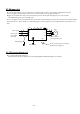
Inverter Service Manual


No. English
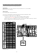
1 CB circuit / DC bus capacitor circuit
2 CB board / DC bus capacitor board
3 Instantaneous power failure detection
4 Phase failure detection
5 Opt coupler / Photo coupler
6 Reference voltage
7 Inrush current limiting (circuit)
8 Thyrister drive circuit (Suppressing circuit)
9 Power supply for Thyrister gate
10 Control signal for Thyrister
11 BRD drive circuit (incl. Short circuit protection)
12 Control signal for BRD
13 Short circuit detection
14 Power supply for lower arm IGBTs
15 Drive circuit for lower arm IGBTs (incl.Short circuit detection)
16 Drive circuit for upper arm IGBTs (incl.Short circuit detection)
17 Power supply for U phase
18 Current detection for U phase
19 Current detection for W phase
20 Control power supply
21 Temperature detection
22 Control power supply
23 Power supply for GA (Gate Array)
24 Power supply for I/F (interface)
25 UV (Under voltage) detection
26 Instantaneous power failure detection
27 Dividing circuit
28 OV (Over voltage) detection
29 Voltage detection for earch phase
30 f,sita detection
31 Main PCB
32 High speed opt coupler
33 Isolation amplifier
34 30 connections between main PCB and logic PCB
35 "H" while BRD ON
36 Approx. 3.3V peak at rated current
37 "L" while Inverter trips
38 "L" while phase failure
39 Communication signal,operates while standstill
40 PWM signal
41 Approx. 6.4V at OV level
42 "L" while stopped by Gate suppressing
43 Signal for frequency matching
44 Control power supply for digital portion
45 Control power supply for analog portion
46 Power supply for I/F (interface)
47 "H" while instantaneous power failure
48 OC(Over current)detection
49 Hardware latch
50 25 control terminals
51 31 control terminals
52 Logic PCB