
Network Card User Manual


Chapter 2
Chapter 2 – Installation and Wiring
Orientation to Product Features
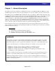
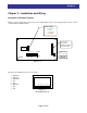
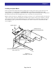
Figure 2-1 below shows the physical layout of the SJ-EN Ethernet option board. In particular, note the location
of status LEDs and DIP-switches.
RJ45
Jack
DIP Switches
Connector to
connect to
SJ300 or L300P
(
rear of board
)
SJ-EN
7 6 5 4 3 2 1 0
STATUS LEDs
• STATUS
• LINK
• ACTIVITY
• ERROR
OFF
ON
TXD LED
RXD LED
SJ-EN Layout
Figure 2-1
The pinout for the RJ45 connector is as follows:
1. TX Data +
8 7 6 5 4 3 2 1
Figure 2-2
SJ-EN RJ45 Pinouts
2. TX Data –
3. RX Data +
4. NC
5. NC
6. RX Data –
7. NC
8. NC
Page 9 of 36