
user manual


3.5.7
3 - 57
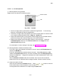
3.5.7 Operation of the Specimen Stage (Type II - 5-Axis Motorized Stage)
The S-3400N Type II SEM provides a 5-axis motorized stage.
3.5.7.1 Coordinate Notation
S-3400N utilizes two coordinate notation systems, Stage (Mechanical) Coordinate and Sample
Coordinate. The Sample Coordinate system will be better for using the Rotation Assist
function. The Stage Coordinate system is also available for users familiar with previous Hitachi
SEMs using the Stage Coordinate system.
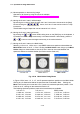
(1) Relationship of stage and Sample Coordinates
Following is an example of a 5 inch diameter sample.
On the Stage Coordinate system, the center of the sample is (X=60, Y=25 mm) and the
origin is at the upper-left corner of XY movable area.
On the Sample Coordinate system, the center of the sample is the origin (X=0, Y=0 mm)
and the origin fits to it.
(
60, 25
)
(0, 0)
(0, 50)
(60, -26)
(
9, 25
)
(
100, 50
)
(100, 0)
(
60, 76
)
X
Y
∅
102 mm sample
Movable range of stage
(111, 25)
(
100, 25
)
(0, 0)
(-60, 25)
(-60, -25)
(40, 25)
(-60, 0)
(-51, 0)
(40, 0)
(40, -25)
(
0, -51
)
X
Y
∅102 mm sample
Movable range of stage
(0, 51)
Stage coordinates (mechanical coordinates) Sample coordinates
Fig. 3.5-27 Relationship between the Two Coordinate Systems
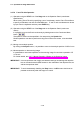
(2) Switching coordinate systems
Open the Optional Setup dialog window by selecting Stage command in Optional Setup
menu.
On the COORDINATE area, select Sample or Stage. OK button will update the coordinate
system.