
user manual


3.5.7
3 - 65
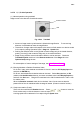
(8) Position display
The size of the specimen, its present position and rotation angle are displayed on the XYR
position monitor area.
Fig. 3.5-35 Position Display
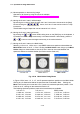
When sample and stage coordinates are selected, the following scale values apply; the
example below applies to a ∅15 mm sample.
When the specimen is moved, the numbers associated with the vertical and horizontal axes
at the intersection of the red cross epresent the coordinates of the position that is being
irradiated by the beam. The numbers change when the specimen size is changed.
Sample coordinates Stage coordinates
Fig. 3.5-36 Differences of values displayed in sample position monitor
Straightline on specimen circle: Angle of specimen rotation.
Directl
y
above at 0°.
Green rectangle: Scanning direction of electron beam on specimen.
Turns by raster rotation. Red circle corresponds to
u
pp
er left
p
os. on screen.
Red cross cursor intersection: Electron beam irradiation position
Blue square: Observable area on the specimen.
White circle: S
p
ecimen stub