
user manual


4.8.1
4 - 35
(2) Set the acceleration voltage to 5 kV. With the Filament Image mode on (with an elliptic
image displayed), set the Probe Current to 100.
Make sure that the objective lens movable aperture is "0".
(3) Set the Filament to approximately 90 (saturation condition).
Turn off Auto Gun Bias.
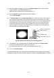
(4) In Filament Image, select the Beam Align Shift. If the image is too bright or dark, adjust
the contrast by using the M4 screw (using an M4 hex wrench) of the electron gun so that
the bright spot is brought to the center of the screen. See Fig. 4.8-2 on the right. Be careful
that the M4 screw is not confused with a transport screw or the C-lens adjustment screw.
If the C lens adjustment screw is moved by mistake, the C-lens current center can shift,
causing a significant change in system performance. The operation should be performed
with great care to avoid this type of problem.
Fig. 4.8-2 Adjusting the electron gun mounting position
(5) Fix the electron gun mounting position screws when the image in the Filament Image
assumes the condition shown in Figure 4.8-2 on the left.
To avoid over-tightening, secure the screws diagonally a little at a time.
(6) Turn off the Filament Image
This concludes the electron gun mounting position adjustment process. Confirm that the image
is displayed normally when the acceleration voltage is modified or the Probe Current is changed.
Electron gun adjustment
screw (4 places)
Transport screw
C-lens adjustment screw