
Brochure


10
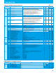
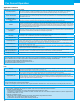
Function List
C Group: Intelligent Terminal Functions
Function Code Name Range Default Unit
Run mode edit
Lo Hi
Intelligent
input
terminal
C001 Terminal [1] function
00(FW:Forward), 01(RV:Reverse), 02-04(CF1-CF3:Multispeed command), 06(JG:Jogging),
07(DB:External DC braking), 08(SET:Second motor constants setting),
09(2CH:Second accel./decel.), 11(FRS:Free-run stop), 12(EXT:External trip),
13(USP:Unattended start protection), 15(SFT:Software lock), 18(RS:Reset),
20(STA:3-wire start), 21(STP:3-wire stop), 22(F/R:3-wire fwd./rev.), 23(PID:PID On/Off),
24(PIDC:PID reset), 27(UP:Remote-controlled accel.), 28(DWN:Remote-controlled decel.),
29(UDC:Remote-controlled data clearing), 31(OPE:Operator control),
32 -34(SF1-SF3: multispeed bit1, 39 (OLR: overload restriction selection),
50(ADD: Frequency setpoint), 51(F-TM: Force terminal enable),
53(S-ST: Special-Set (select) 2nd Motor Data), 65 (AHD: analog command holding),
83 (HLD: retain output frequency), 84 (ROK: permission of run command),
86 (DISP: display limitation),255(NO:Not selected),
00
-
X
C002 Terminal [2] function 01
-
X
C003 Terminal [3] function 02
-
X
C004 Terminal [4] function 03
-
X
C005 Terminal [5] function 18
-
X
C011- C015
Terminal [1] to [5] active state 00(NO)/01(NC) 00
-
X
Intelligent
input
terminal
C021 Terminal [11] function
00(RUN:run signal), 01(FA1:Frequency arrival type 1 - constant speed),
02(FA2:Frequency arrival type 2 - over-frequency), 03(OL:overload advance notice
signal), 04(OD:Output deviation for PID control), 05(AL:alarm signal), 06(DC:Wire brake
detect on analog input), 09(LOG: Logic operation result),11 (RNT: run time expired),
12 (ONT: power ON time expired), 13 (THM: thermal warning), 21 (ZS: 0Hz detection),
27 (ODc: Analog input disconnect detection),31 (FBV: PID second stage output),
32 (NDc: Network disconnect detection), 33 (LOG1: Logic output function 1),
41 (FR: Starting contact signal), 42 (OHF: Heat sink overheat warning),
50 (IRDY:Inverter ready), 51 (FWR:Forward rotation), 52 (RVR:Reverse rotation),
53 (MJA:Major failure), 54 (WCO: Window comparator),
58(FREF: Frequency command source), 59(REF: Run command source),
60(SETM:Second motor in operation),255(NO: Not selected)
01
-
X
C026 Alarm relay function 05
-
X
C027 FM signal selection (Pulse/PWM output)
00 (output frequency), 01 (output current), 03 (digital output frequency), 04 (output
voltage), 05 (input power), 06 (electronic thermal overload), 07 (LAD frequency), 08
(digital current monitoring), 10 (heat sink temperature)
07
-
X
C030 Digital current monitor reference value 0.20 × rated current to 2.00 × rated current
Rated current
A
C031 Terminal [11] active state 00(NO)/01(NC) 00
-
X
C036 Alarm relay active state 00(NO)/01(NC) 01
-
X
C038 Output mode of low load detection signal
00 (output during acceleration/deceleration and constant-speed operation)/
01 (output only during constant-speed operation)
01
-
X
C039 Low load detection level 0.00 to 2.00 × Rated current to 2.00 × rated current
Rated current
A
C040 Output mode of overload warning
00 (output during acceleration/deceleration and constant-speed operation)/
01 (output only during constant-speed operation)
01
-
X
C041 Overload level setting
0.00 × Rated current to 2.00 × Rated current
115% of
Rated current
A
C241 Overload level setting, 2nd motor
C042 Frequency arrival setting for acceleration 0.00 to 99.99/100.0 to 400.0 0.00 Hz
X
C043 Frequency arrival setting for deceleration 0.00 to 99.99/100.0 to 400.0 0.00 Hz
X
C044 PID deviation level setting 0.0 to 100.0 3.0 %
X
C052 Feedback comparison upper level 0.0 to 100.0 100.0 %
X
C053 Feedback comparison lower level 0.0 to 100.0 0.0 %
X
C061 Electronic thermal warning level 0. to 100. 90. %
X
C063 Zero speed detection level 0.00 to 99.99/100.0 0.00 Hz
X
C064 Heat sink overheat warning 0. to 110. 100. ℃
X
Serial
communication
C070 SELECTION OF OPE/MODBUS 00(OPE)/01(Modbus) 00
-
X
C071 Communication speed 04(4800bps)/ 05(9600bps)/ 06(19.2kbps)/07(38.4kbps) 05 bps
X
C072 Node allocation 1 to 247 1.
-
X
C074 Communication parity selection 00(No parity)/01(Even parity)/02(Odd parity) 00
-
X
C075 Communication stop bit selection 01(1-bit)/02(2-bit) 01 bit
X
C076 Communication error mode
00(Trip)/01(Tripping after decelerating and stopping the motor)/02(Disable)/
03(FRS)/04(Deceleration stop)
02
-
X
C077 Communication error time-out 0.00(disabled)/0.01 to 99.99 0.00 s
X
C078 Communication wait time 0. to 1000. 0. ms
X
Analog
meter setting
C081 O/OI input span calibration 0.0 to 200.0 100.0 %
Others
C091 Debug mode enable 00(MD0)/01(MD1) 00
- - -
C101 Up/Down memory mode selection
00 (not storing the frequency data)/ 01 (storing the frequency data)
00
-
X
C102 Reset mode selection
00(Cancel trip state at input signal ON transition)/ 01(Cancel trip state at signal OFF
transition)/02(Cancel trip state at input signal ON transition)
00
-
C103 Restart mode after reset 00 (starting with 0 Hz)/ 01 (restarting with active matching frequency) 00
-
X
C104 UP/DWN clear: terminal input mode selection 00(0Hz)/01(Flash data when power supply is turned on) 00
-
X
C105 FM gain adjustment 50. to 200. 100. %
C130 Output 11 on-delay time 0.0 to 100.0 0.0 s
X
C131 Output 11 off-delay time 0.0 to 100.0 0.0 s
X
C140 Output RY on-delay time 0.0 to 100.0 0.0 s
X
C141 Output RY off-delay time 0.0 to 100.0 0.0 s
X
C142 Logical output signal 1 selection 1 Same as the settings of C021 to C026 (except those of LOG1 to LOG3 & OPO , no) 00
-
X X
C143 Logical output signal 1 selection 2 Same as the settings of C021 to C026 (except those of LOG1 to LOG3 & OPO , no) 00
-
X X
C144 Logical output signal 1 operator selection 00(AND)/01(OR)/02(XOR) 00
-
X
C151 Button sensitivity selection 0 to 250 / no 10
-
X
C152 Scroll sensitivity selection 1 to 20 10
-
X
C155 Ground fault set 00(OFF) / 01(ON) 01
-
X
C157 Out phase-loss set 00(OFF) / 01(ON) 00
-
X
C160 Response time of intelligent input terminal 1 0. to 200. (×2ms) 1.
-
X
C161 Response time of intelligent input terminal 2 0. to 200. (×2ms) 1.
-
X
C162 Response time of intelligent input terminal 3 0. to 200. (×2ms) 1.
-
X
C163 Response time of intelligent input terminal 4 0. to 200. (×2ms) 1.
-
X
C164 Response time of intelligent input terminal 5 0. to 200. (×2ms) 1.
-
X
C169 Multistage speed determination time 0. to 200. (×10ms) 0. ms
: Allowed
[
X
: Not allowed
]
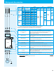
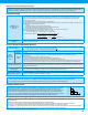
H Group: Motor Constants Functions
: Allowed
[
X
: Not allowed
]
Function Code Name Range Default Unit
Run mode edit
Lo Hi
Motor
constants
and gain
H003 Motor capacity, 1st motor
0.1/0.2/0.4/0.55/0.75/1.1/1.5/2.2/3.0/3.7/4.0/5.5
Factory
set
kW
X X
H203 Motor capacity, 2nd motor
kW
X X
H004 Motor poles setting, 1st motor
2/4/6/8
4 poles
X X
H204 Motor poles setting, 2nd motor
4 poles
X X
H006 Motor stabilization constant
0. to 255.
100.
-
H206 Motor stabilization constant, 2nd motor
100.
-