
User Manual

Chapter 7 Explanation of Functions
7 - 34
7.5.18 PID function
The PID function allows you to use the inverter for the process control on fluid flow, airflow, and pressure.
To enable this function, specify "01 enabled" or "02 inverted data output enabled" for function "A071".
You can disable the PID function with an external signal during the PID operation. For this purpose, assign
function "23" (PID terminal: disabling PID operation) to an intelligent input terminal. Turning the PID
terminal on disables the PID function and makes the inverter perform the normal output.
With the PID function, you can limit the PID output according to various conditions.
maximum frequency, frequency limiter, PID variation range (A078).
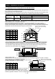
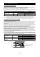
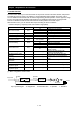
Item Function code Data or range of data Description
PID Function Enable A071
00 Disabling the PID operation
01 Enabling the PID operation
02 Enabling inverted-data output
PID proportional gain A072 0.2 to 25.0 Proportional gain
PID integral time constant A073 0.0 to 3600.(s) Integrated gain
PID derivative gain A074 0.00 to 100.0(s) Derivative gain
PV scale conversion A075 0.01 to 99.99
Scale for unit conversion of PID feedback
data
PV source setting A076
01 O/OI-L: [0 to 10 V]/[4-20mA]
02 Modbus communication
10 Operation result (*1)
Reverse PID action A077
00 Disabling the inverted output
01
Enabling the inverted output (deviation
polarity inverted)
PID variation range A078 0.0 to 100.0(%)
Range of PID data variation with
reference to the target value
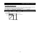
PID sleep function action
threshold
A156 0.0 to 400.0(Hz)
When PID output drops below the
operating level, to stop the behavior.
PID sleep function action
delay time
A157 0.0 to 25.5(s) Delay to the start of the operation of
sleep
PID sleep function return
threshhold
A158 A156 to 400.00Hz Level of return sleep behavior
PID deviation level setting C044 0.0 to 100.0(%) Level to determine the OD signal output
Off level of feedback
comparison signal
C052 0.0 to 100.0(%) Level to determine the FBV signal output
Onlevel of feedback
comparison signal
C053 0.0 to 100.0(%) Level to determine the FBV signal output
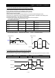
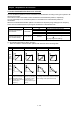
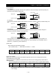
(1) Basic configuration of PID control
Kp: Proportional gain Ti: Integral time Td: Derivative time s: Operator ε: Deviation
fs
M
=
+
-
Target value
Deviation
(ε)
Feedback 0 to 10 V
4 to 20 mA
Operation
quantity
Normal control
by the inverter
Transducer
Sensor
Kp+ +Td・S
1
Ti・S