
User Manual


Chapter 8 Communication Functions
8 - 2
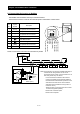
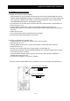
8.2 Connecting the Inverter to Modbus
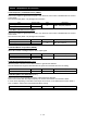
The Modbus communication uses a pin of RJ45 as below.
The the RJ45 connector is used for the external operator and Modbus communication.
Please connect each inverter like the chart below in parallel.
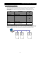
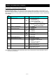
Pin
No:
Signal
Symbol
Description
1 DC+5V For Operator. Do not connect.
2 ― For Operator. Do not connect.
3 ― For Operator. Do not connect.
4 SG(GND) Signal Ground
5
SP
Send Data Positive
6
SN
Send Data Negative
7 (GND) For Operator. Do not connect.
8 ― Not used. Do not connect.
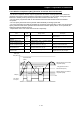
Note) Communication may become unstable depending on
a cable and the wiring situation to use for use
environment of the inverter, a communication line. In
that case, please carry out follows.
- not use the terminal resistance with a built-in
inverter, and please get the terminal resistance
that matched the characteristic impedance of the
cable at the both ends of the communications
cable.(the terminal resistance having built-in to
inverter is 100 Ω.)
- Please connect a signal ground of each inverter
to external equipment (master).
- Please lower a transfer speed.
- Please insert a repeater.
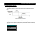
1) Do not connect
2) Do not connect
3) Do not connect
4) SG(GND)
5) SP
6) SN
7) Do not connect
8) Do not connect
SP SN SP SN SP SN
Host device
(Master)
+ -
NE-S1
(
No.2
)
NE-S1
(
No.3
)
NE-S1
(
No.n
)
SG
L L L
SP
SN
NE-S1
(
No.1
)
termination
resistors
100Ω
L