
User Manual


Chapter 8 Communication Functions
8 - 11
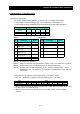
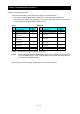
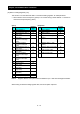
The data set in the response is as follows:
Response Buffe
r
4-5 6-7 8-9
Register Number 12+0 (high
order)
12+0
(low
order)
12+1
(high
order)
12+1 (low
order)
12+2
(high
order)
12+2 (low
order)
Register Data 0003h 04h 0000h
Trip data Trip factor (E03) Status Frequency (9.9Hz)
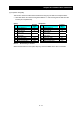
Response Buffe
r
10-11 12-13 14-15
Register Number 12+3 (high
order)
12+3
(low
order)
12+4
(high
order)
12+4 (low
order)
12+5
(high
order)
12+5 (low
order)
Register Data 0063h 001Eh 011Ch
Trip data Frequency (9.9Hz) Output current (3.0A) DC-bus voltage (284V)
When the Read Holding Register command cannot be executed normally, refer to the exception
response.
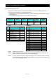
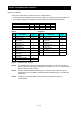
(C) Write in Coil [05h]
This function writes data in a single coil. Coil status changes are as follows:
Data
Coil Status
OFF to ON ON to OFF
Change data (high order) FFh 00h
Change data (low order) 00h 00h
An example follows (note that to command the inverter, set A002=03):
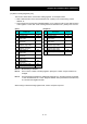
Sending a RUN command to an inverter having slave address “8”
This example writes in coil number “1.”
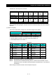
Query: Response:
No. Field Name
Example
(Hex)
No. Field Name
Example
(Hex)
1 Slave address *1 08 1 Slave address 08
2 Function code 05 2 Function code 05
3 Coil start address *2
(high order)
00 3 Coil start address *2
(high order)
00
4 Coil start address *2
(low order)
00 4 Coil start address *2
(low order)
00
5 Change data
(high order)
FF 5 Change data
(high order)
FF
6 Change data
(low order)
00 6 Change data
(low order)
00
7 CRC-16 (high order) 8C 7 CRC-16 (high order) 8C
8 CRC-16 (low order) A3 8 CRC-16 (low order) A3
Note 1: No response is made for a broadcasting query.
Note 2: The PDU Coils are addressed starting at zero. Therefore coils numbered 1-86 are
addressed as 0-85. Coil address value (transmitted on Modbus line) is 1 less than the
Coil Number.
When writing in a selected coil fails, see the exception response.