
User Manual

Chapter 7 Explanation of Functions
7 - 13
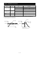
7.3.3 Input terminal response time
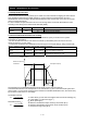
- The input terminal response time function allows you to specify a sampling time for each of intelligent input terminals
1 to 5. You can use this function effectively to remove noise (e.g., chattering).
- If chattering hinders constant input from an input terminal, increase the response time setting for the input terminal.
Note that an increase in response time deteriorates the response. The response time can be set in a range of about 2
to 400 ms (corresponding to settings of 0 to 200).
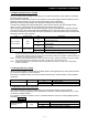
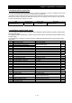
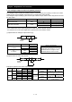
Item Function code Range of data Description
Response time of intelligent
input terminals 1 to 5
C160-C164 0. to 200. Variable in step of 1
Note: When the power supply is OFF-> ON or reset , this function is invalid.
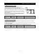
7.3.4 Intelligent output terminal setting
You can assign the functions described below to the intelligent output terminals [11] (C021) and the alarm
relay terminal (C026).
The intelligent output terminals [11] is used for open-collector output, and the alarm relay terminal is used
for relay output.
You can select the a-contact or b-contact output for individual output terminals by using functions "C031"
and "C036".
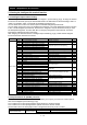
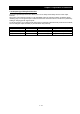
Data Description Reference item Page
00 RUN: Running signal Running signal (RUN) 7-68
01 FA1: Constant-speed reached
Frequency-arrival signals 7-68
02 FA2: Set frequency overreached
03 OL: Overload notice advance signal Overload restriction/overload notice advance signal 7-63
04 OD: Output deviation for PID control PID function 7-37
05 AL: Alarm signal Protective functions -
06 FA3: Set frequency reached Frequency-arrival signals 7-68
09 UV: Undervoltage undervoltage 7-53
11 RNT: Operation time over Operation time over signal 7-70
12 ONT: Plug-in time over Plug-in time over signal 7-70
13 THM: Thermal alarm signal Electronic thermal protection 7-62
21 ZS: 0 Hz detection signal 0 Hz detection signal 7-70
27 Dc: Analog O/OI disconnection detection Window comparators function 7-75
31 FBV: PID feedback comparison PID function 7-34
32 NDc: Communication line disconnection RS485 7-72
33 LOG1: Logical operation result 1 Logical operation function 7-71
41 FR: Starting contact signal Starting contact signal 7-72
42 OHF: Heat sink overheat warning Heat sink overheat warning 7-72
43 LOC: Low-current indication signal Low-current indication signal 7-73
50 IRDY: Inverter ready Inverter ready signal 7-73
51 FWR: Forward rotation Forward rotation signal 7-73
52 RVR: Reverse rotation Reverse rotation signal 7-74
53 MJA: Major failure Major failure signal 7-74
54
WC:Window Comparator for Analog Voltage
Input
Window comparators function 7-75
58 FREF:Frequency Command Source Frequency Command Source signal 7-76
59 REF:Run Command Source Run Command Source signal 7-76
60 SETM:2nd Motor Selection 2nd Motor Selection signal 7-76
no NO: Allocation none
-