
Brochure

3
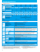
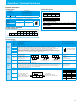
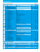
Standard Specifications
1-/3-phase 200V class
3-phase 400V class
General Specifications
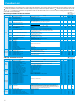
Model NES1-
002SB 004SB 007SB 015SB 022SB
002LB 004LB 007LB 015LB 022LB
Output
Ratings
Applicable motor size, 4-pole kW(HP) *1 0.2(1/4) 0.4(1/2) 0.75(1) 1.5(2) 2.2(3)
Rated capacity
200V 0.4 0.9 1.3 2.4 3.4
240V 0.5 1.0 1.6 2.9 4.1
Rated output current (A) *2 1.4 2.6 4.0 7.1 10.0
Overload capacity(output current) 150% for 60 sec.
Rated output voltage (V) 3-phase (3-wire) 200 to 240V (corresponding to input voltage)
Input Rating
Rated input voltage (V)
SB: 1-phase 200 to 240V+10%, -15%, 50/60Hz ±5%
LB: 3-phase 200 to 240V+10%, -15%, 50/60Hz ±5%
Rated input current (A)
SB
3.1 5.8 9.0 16.0 22.5
LB
1.8 3.4 5.0 9.3 13.0
Enclosure *4 IP20
Cooling method Self-cooling Force ventilation
Weight (kg)
SB
0.7 0.8 1.0 1.2 1.3
LB
0.7 0.8 0.9 1.2 1.3
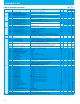
Model NES1- 004HB 007HB 015HB 022HB 040HB
Output
Ratings
Applicable motor size, 4-pole kW(HP) *1 0.4(1/2) 0.75(1) 1.5(2) 2.2(3) 4.0(5)
Rated capacity (kVA)
380V 0.9 1.6 2.6 3.6 6.0
480V 1.2 2.0 3.4 4.5 7.6
Rated output current (A) *2 1.5 2.5 4.1 5.5 9.2
Overload capacity(output current) 150% for 60 sec.
Rated output voltage (V) 3-phase (3-wire) 380 to 480V (corresponding to input voltage)
Input Rating
Rated input voltage (V) 3-phase 380 to 480V +10%, -15%, 50/60Hz ±5%
Rated input current (A) 2 3.3 5.2 7 11.7
Enclosure *4 IP20
Cooling Method Self-cooling Force ventilation
Weight (kg) 0.9 1.0 1.1 1.2
Item General Specifications
Control
Control method Line-to-line sine wave pulse-width modulation (PWM) control
Output frequency range *5 0.01 to 400Hz
Frequency accuracy *6 Digital command :±0.01%, Analog command
±
0.4% (25
±
10˚C)
Frequency setting resolution Digital: 0.01Hz, Analog: (max frequency)/1000
Voltage/Frequency Characteristic V/f control,V/f variable (constant torque, reduced torque)
Acceleration/deceleration time 0.00 to 3000 sec. (linear, sigmoid), two-stage accel./decel.
Starting torque *7 100%/6Hz
Carrier frequency range 2.0 to 15kHz
Protective functions
Over-current, Over-voltage, Under-voltage, Overload, Overheat, Ground fault at power-on, Input over-voltage, External
trip, Memory error, CPU error, USP error, Driver error, Output phase loss protection
Input
terminal
Specification
10kohm input impedance, sink/source logic selectable
Functions
FW(Forward), RV(Reverse), CF1-CF3(Multispeed command), JG(Jogging), DB(External DC braking), SET(Second motor
constants setting), 2CH(Second accel./decel.), FRS(Free-run stop), EXT(External trip), USP(Unattended start protection),
SFT(Software lock), AT(Analog input selection), RS(Reset), STA(3-wire start), STP(3-wire stop),
F/R(3-wire fwd./rev.), PID(PID On/Off), PIDC(PID reset), UP/DWN(Remote-controlled accel./decel.) , UDC(Remote-controlled
data clearing), OPE(Operator control), SF1-SF3(multispeed bit), OLR(overload restriction selection), LAC(LAD cancellation,
ADD(ADD frequency enable), F-TM(force terminal mode), KHC(cumulative power clearance), AHD(analog command
holding), HLD(retain output frequency), ROK(permission of run command), DISP (display limitation), NO(Not selected)
Output signal
Intelligent output
terminal
Specification
27V DC 50mA max open collector output, 1 terminals 1c output relay (AL0, AL1, AL2 terminals)
Function
RUN(run signal), FA1(Frequency arrival type 1 - constant speed), FA2(Frequency arrival type 2 - over-frequency),
OL(overload advance notice signal), OD(Output deviation for PID control), AL(alarm signal), DC(Wire brake detect on
analog input), FBV(PID Second Stage Output), NDC(ModBus Network Detection Signal), LOG(Logic Output Function),
ODC(analog voltage input disconnection), LOC(Low load), FA3(Set frequency reached), UV(Under voltage),
RNT(Operation time over), ONT(Plug-in time over), THM(Thermal alarm signal), ZS(0 Hz detection signal),
IRDY(Inverter ready), FWR(Forward rotation),RVR(Reverse rotation), MJA(Major failure)
Moniter output terminal
Function
PWM output; Select analog output frequency monitor, analog output current monitor or digital output frequency monitor
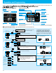
Operator
Operation key
1 unified key for RUN/STOP/RESET
ON : this key has function of "RUN"(regardless run command source setting (A002/A201).)
OFF : this key has function of "STOP/RESET
When optional operator is connected, operation from key is disabled.
Status LED Interface
Control power supply LED (Red),LED during operation (yellow-green),Operation button operation LED (yellow-green),LED
during tripping (Red), 4LED in total
Operation
Frequency
setting
Operator keypad(Option)
Up and Down keys / Value settings or analog setting via potentiometer on operator keypad
External signal *8
0 to 10 V DC or 4 to 20 mA
Serial port
RS485 interface (Modbus RTU)
FW/RV Run
Operator Keypad(Option)
Run key / Stop key (change FW/RV by function command)
External signal
FW Run/Stop (NO contact), RV set by terminal assignment (NC/NO), 3-wire input available
Serial port
RS485 interface (Modbus RTU)
Environment
Operating temperature
-
10 to 50℃(carrier derating required for aambient temperature higher than 40℃(022SB:temperature higher than 30℃)),
no freezing
When attach option FFM, in 015/022SB the derating becomes needless.
Storage temperature
-
20 to 60˚C
Humidity
20 to 90% RH
Vibration
5.9mm/s
2
(0.6G) 10 to 55Hz
Location
Altitude 1,000 m or less, indoors (no corrosive gasses or dust)
Other functions
AVR (Automatic Voltage Regulation), V/f characteristic selection, accel./decel. curve selection, frequency upper/lower limit,
8 stage multispeed, PID control, frequency jump, external frequency input bias start/end, jogging, trip history etc.
Options
Remote operator with copy function (WOP), Remote operator (OPE-SRmini, OPE-SR), Operator (NES1-OP),
input/output reactors, DC reactors, radio noise filters, LCR filter, communication cables (ICS-1, 3)
Note 1: The applicable motor refers to Hitachi standard 3-phase motor (4-pole). When using other motors, care
must be taken to prevent the rated motor current (50/60 Hz) from exceeding the rated output current of
the inverter.
Note 2: The output voltage decreases as the main supply voltage decreases (except when using the AVR
function). In any case, the output voltage cannot exceed the input power supply voltage.
Note 3: The braking torque via capacitive feedback is the average deceleration torque at the shortest
deceleration (stopping from 50/60 Hz as indicated). It is not continuous regenerative braking torque.
The average decel torque varies with motor loss. This value decreases when operating beyond 50 Hz.
Note 4: The protection method conforms to JIS C 0920(IEC60529).
Note 5: To operate the motor beyond 50/60 Hz, consult the motor manufacturer for the
maximum allowable rotation speed.
Note 6: The output frequency may exceed the maximum frequency setting (A004 or
A204) for automatic stabilization control.
Note 7: At the rated voltage when using a Hitachi standard 3-phase, 4pole motor.
Note 8: DC 4 to 20 mA Input, need parameter setting by Keypad etc.
Analog input voltage or current can be switched by switch as individually and not
use them in the same time.