
Brochure

6
-
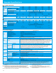
Operation / Terminal Functions
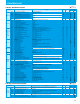
Terminal Description
Terminal Symbol
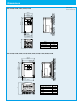
R(L1) S(L2) T(L3) P(+)
U(T1) V(T2) W(T3) PD(+1)
L1 N P(+)
U(T1) V(T2) W(T3) PD(+1)
●
NES1-002-007LB
●
NES1-002,004SB
R(L1) S(L2) T(L3) PD(+1) P(+) U(T1) V(T2) W(T3)
L1 N PD(+1) P(+) U(T1) V(T2) W(T3)
●
NES1-015,022LB,004-040HB
●
NES1-007-022SB
Screw Diameter and Terminal Width
Terminal Arrangement
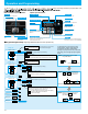
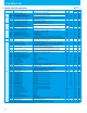
Control Circuit Terminals
Terminal Arrangement
Short bar:default position (Source logic)
AL2 AL1 AL0 H O/OI L FM L PLC P24
5 4 3 2 1 CM2 11
Terminal Function
(1kΩ
-
2kΩ)
DC0
-
10V
Input inpedance 10kΩ
DC4
-
20mA
Input inpedance 250Ω
VR
H
O/OⅠ
L H
O/OⅠ
L
+ −
H
O/OⅠ
L
+ −
SW
L
1-5
Operated by closing switch.
(Input logic is selectable)
AL2 AL1 AL0
Relay contact (alarm output)
terminals (programable,
function is selectable same as
intelligent output terminals).
<Initial setting>
Normal: AL0-AL1 closed
Trip/Power OFF : AL0-AL2 closed
Resistance load
Inductive load
AL1-AL0
Maximum contact
capacity
250V AC, 2A
30V DC, 3A
250V AC, 0.2A
30V DC, 0.6A
Minimum contact
capacity
100 V AC, 10mA
5 V DC, 100mA
AL2-AL0
Maximum contact
capacity
250V AC, 1A
30V DC, 1A
250V AC, 0.2A
30V DC, 0.2A
Minimum contact
capacity
100 V AC, 10mA
5 V DC, 100mA
Terminal name
Input/monitor
signals
FM Monitor terminal (frequency, current, etc.) PWM out put(0 to10V DC, 1mA max.)
L Common for inputs
-
P24 +24V for logic inputs
24V DC, 30mA (do not short to terminal L)
PLC Intelligent input common
-
5
Intelligent (programable) input terminals, selection from: FW(Forward), RV(Reverse), CF1-CF3(Multispeed command),
JG(Jogging),
DB(External DC braking), SF1-SF3(multispeed bit), SET(Second motor constants setting), 2CH(Second accel./decel.),
FRS(Free-run stop), EXT(External trip), USP(Unattended start protection), SFT(Software lock), RS(Reset), STA(3-wire start),
STP(3-wire stop), F/R(3-wire fwd./rev.), PID(PID On/Off), PIDC(PID reset), OLR(overload restriction selection),
UP/DWN(Remote-controlled accel./decel.), UDC(Remote-controlled data clearing), OPE(Operator control), ADD(Frequency setpoint),
F-TM(Force terminal enable),KHC(cumulative power clearance), AHD(analog command holding), HLD(retain output frequency),
ROK(permission of run command), DISP (display limitation) or NO(Not selected).
4
3
2
1
Freqency
setting
H +10V analog reference 10V DC, 10mA max
O/OI
Analog input, voltage/
Analog input, current
Switch able by switch but not use
them in the same time.
0 to 10V DC,
input impedance10kohm
4 to 20mA DC,
input impedance 250ohm
L Common for inputs
-
Output
signals
11
Intelligent (programable) output terminals, selection from:
RUN(run signal), FA1(Frequency arrival type 1 -constant speed), FA2(Frequency arrival type 2 -over-frequency), OL(overload advance
notice signal), OD(Output deviation for PID control), AL(alarm signal), FA3(Set frequency reached), UV(Under voltage), RNT(Operation time
over), ONT(Plug-in time over), DC(Wire brake detect on analog input), FBV(Feedback voltage comparison), NDc(analog voltage input
disconnection), LOG1(Logic operation result), LOC(Low Load Detection).
Open collector output
L level at operation (ON)
27V DC, 50mA max.
CM2 Common for intelligent output terminals
-
Relay
output
AL2
AL1
AL0
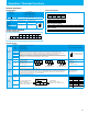
Model Screw diameter (mm) Terminal width W (mm)
002-004SB
M3.5 7.1
002-007LB
007-022SB
M4 9.2015-022LB
004-040HB
Terminal Symbol Terminal Name
L1,L2,N/L3 Main power supply input terminals
U/T1,V/T2,W/T3 Inverter output terminals
+1,+
DC reactor connection terminals
Ground connection terminal