CP-X880W / CP-X885W USER'S MANUAL, Vol. 1 Please read this user's manual thoroughly to ensure correct usage through understanding. Downloaded from www.Manualslib.
LCD Projector CP-X880/CP-X885 USER'S MANUAL Vol.1 (Basic) Thank you for purchasing this projector. WARNING • Please read the accompanying manual “SAFETY INSTRUCTIONS” and this “USER'S MANUAL” thoroughly to ensure correct usage through understanding. After reading, store this instruction manual in a safe place for future reference. NOTE • The information in this manual is subject to change without notice.
PROJECTOR FEATURES This liquid crystal projector is used to project various computer signals as well as NTSC / PAL / SECAM video signals onto a screen. Little space is required for installation and large images can easily be realized.
WARNING Precautions to observe in regards to the power cord: Please use extra caution when connecting the projector's power cord as incorrect or faulty connections may result in FIRE AND/OR ELECTRICAL SHOCK. Please adhere to the following safety guidelines to insure safe operation of the projector: • Only plug the power cord into outlets rated for use with the power cord's specified voltage range. • Only use the power cord that came with the projector.
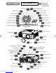
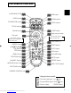
THE PROJECTOR PART NAMES Indicates the corresponding reference page KEYSTONE button INPUT dial ONE TOUCH button RGB indicator RESET button BNC indicator DVI indicator RGB INPUT FOCUS button KEYSTONE BNC VIDEO indicator FOCUS VIDEO S-VIDEO indicator ZOOM RESET MENU button S-VIDEO COMPONENT COMPONENT indicator ZOOM button ONE TOUCH DVI STANDBY/ON STANDBY/ON button MENU LAMP indicator Vol.2 TENP LANP Control Panel TEMP indicator Vol.
THE REMOTE CONTROL LASER INDICATOR RGB button VIDEO button STANDBY/ON button LASER INDICATOR STANDBY/ON VIDEO ZOOM buttons RGB PAGE buttons UP FOCUS buttons FOCUS ZOOM PAGE DOWN BLANK button LASER BLANK LASER button Right mouse button Disk pad Mouse cursor movement Left mouse click Right mouse click ASPECT Lever switch (*) ASPECT button RESET button PUSH Left /Right Key buttons ESC button ENTER ESC MENU RESET POSITION AUTO PinP PinP b
SETTING UP THE PROJECTOR CAUTION • Install the projector in a suitable environment according to instructions of the accompanying manual “SAFETY INSTRUCTIONS” and this manual. • If you press the elevator buttons without holding the projector, the projector might crash down, overturn, smash your fingers and possibly result in malfunction. To prevent damaging the projector and injuring yourself, ALWAYS HOLD THE PROJECTOR whenever using the elevator buttons to adjust the elevator feet.
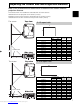
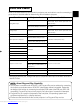
Adjusting the Screen Size and Projection Distance Refer to the illustrations and tables below to determine the screen size and projection distance. The values shown in the table are calculated for a full size screen a:Distance from the projector to the screen (±10%) b:Distance from the lens center to the bottom of the screen (±10%) c:Distance from the lens center to the top of the screen (±10%) The screen Top view If 4:3 aspect ratio 4 3 Screen Size [inch (m)] 30 (0.8) 40 (1.0) 50 (1.3) 60 (1.5) 70 (1.
CONNECTING YOUR DEVICES Devices You Can Connect to the Projector (Refer to this section for planning your device configuration to use for your presentation.) CAUTION • Incorrect connecting could result in fire or electrical shock. Please read this manual and the separate “SAFETY INSTRUCTIONS”. ATTENTION Precautions to observe when connecting other devices to the projector • Whenever attempting to connect other devices to the projector, please thoroughly read the manual of each device to be connected.
Ports and Cables Refer to the table below to find out which projector port and cable to use for connecting a given device. Use this table for determining which cables to prepare.
CONNECTING YOUR DEVICES (continued) Connecting to a Computer ATTENTION Whenever attempting to connect a laptop computer to the projector, be sure to activate the laptop's RGB external image output (set the laptop to CRT display or to simultaneous LCD and CRT display). For details on how this is done, please refer to the instruction manual of the corresponding laptop computer.
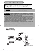
Connecting to a Computer (continued) BNC Input DVI Input REMOTE CONTROL DVI CR/PR RGB R/CR/PR RGB OUT G/Y B/Ca/Pa Ca/Pa Y CONTROL H V BNC REMOTE CONTROL DVI COMPONENT VIIDEO CR/PR RGB R-AUDIO IN-L VIDEO IN 1 2 AUDIO IN AUDIO OUT G/Y B/Ca/Pa USB Y COMPONENT VIIDEO CONTROL H V BNC R-AUDIO IN-L VIDEO IN 1 2 AUDIO IN AUDIO OUT S-VIDEO IN USB AUDIO cable (Stereo mini) AUDIO OUT DVI cable DVI OUT AUDIO cable (Stereo mini) AUDIO OUT BNC cable BNC OUT Desktop computer RGB OUT
CONNECTING YOUR DEVICES (continued) Connecting to a DVD Player Connecting to a VCR REMOTE CONTROL DVI RGB OUT RGB R/CR/PR CR/PR G/Y B/Ca/Pa Ca/Pa Y REMOTE CONTROL COMPONENT VIIDEO CONTROL H BNC CR/PR RGB OUT RGB R-AUDIO IN-L VIDEO IN 1 2 V DVI AUDIO IN AUDIO OUT USB G/Y B/Ca/Pa H V BNC S-VIDEO OUT AUDIO/VIDEO OUT If using a S-video connection Connecting to a Display Monitor REMOTE CONTROL DVI RGB OUT RGB R/CR/PR CR/PR G/Y B/Ca/Pa Ca/Pa Y COMPONENT VIIDEO CONTROL H R-A
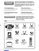
USING THE REMOTE CONTROL Putting batteries into the remote control unit CAUTION Precautions to observe in regards to the batteries Always handle the batteries with care and use them only as directed. Improper use may result in battery cracking or leakage, which could result in fire, injury and/or pollution of the surrounding environment. • Keep the battery away from children and pets. • Be sure to use only the batteries specified for use with the remote control. Do not mix new batteries with used ones.
USING THE REMOTE CONTROL (continued) Operating the remote control WARNING • The laser pointer of the remote control transmitter is used in place of a finger or rod. Never look directly into the laser beam outlet or point the laser beam at other people. The laser beam can cause vision problems. CAUTION • Use of controls or adjustments or performance of procedures other than those specified herein may result in hazardous radiation exposure.
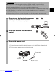
TURNING ON THE POWER Precautions Connect all devices to be used to the projector prior to turning on the power. WARNING When the power is ON, a strong light is emitted. Do not look into the lens. LASER INDICATOR STANDBY/ON VIDEO RGB FOCUS ZOOM PAGE 1 Make sure that the power cord is firmly and correctly connected to the projector and outlet 2 Turn on the projector's power UP DOWN LASER BLANK Set the power switch to [ | ] (ON). The STANDBY/ON indicator will light to solid orange.
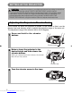
TURNING ON THE POWER (continued) Selecting an Input Signal 5 Using the remote control If selecting RGB input Press the RGB button Turn the INPUT dial Press this button to toggle between the devices connected to RGB IN 1 and 2. As illustrated below, each time you press the RGB button, the projector switches between RGB IN 1 and 2. Select the signal you wish to project.
TURNING OFF THE POWER 1 LASER INDICATOR STANDBY/ON VIDEO RGB The message "Power off?" will appear on the screen for approximately 5 seconds. UP FOCUS Press the STANDBY/ON button (control panel or remote control) STANDBY/ON PAGE ZOOM DOWN BLANK LASER 2 Press the STANDBY/ON button again while the "Power off?" message is visible. The projector lamp goes off and starts cooling down. While cooling, the STANDBY/ON indicator flashes orange.
ADJUSTING THE VOLUME LASER INDICATOR STANDBY/ON VIDEO RGB FOCUS ZOOM PAGE 1 UP Press the VOLUME button VOLUME As illustrated on the right, a dialog will appear on the screen to aid you in adjusting the volume. VOLUME DOWN BLANK LASER 16 2 ASPECT Use the lever switch volume / to adjust the Press the VOLUME button again to close the dialog and complete this operation. (Even if you don't do anything, the dialog will automatically disappear after a few seconds.
ADJUSTING THE POSITION LASER INDICATOR STANDBY/ON VIDEO RGB FOCUS ZOOM PAGE 1 Press the POSITION button As illustrated on the right, a dialog will appear on the screen to aid you in adjusting the position.
USING THE AUTOMATIC ADJUSTMENT FEATURE BLANK LASER 1 AUTO Automatic Adjustment for RGB Input ASPECT PUSH ENTER ESC MENU RESET POSITION AUTO PinP MAGNIFY VOLUME ON FREEZE MUTE OFF WIRELESS Press the AUTO button Horizontal position (H. POSIT), vertical position (V. POSIT), clock phase (H. PHASE) and horizontal size (H. SIZE) are automatically adjusted. Make sure that the application window is set to its maximum size prior to attempting to use this feature.
CORRECTING KEYSTONE DISTORTIONS 1 ASPECT Press the KEYSTONE button As illustrated on the right, a dialog will appear on the screen to aid you in correcting the distortion.
USING THE MAGNIFY FEATURE DOWN BLANK 1 Press the MAGNIFY (ON) button 2 Press the POSITION button, then use the lever switch / , / to select the area to zoom. Press the POSITION button again to finalize the zoom area. The projector enters MAGNIFY mode.
ADJUSTING SCREEN WITH ONE-TOUCH FOCUS ZOOM PAGE DOWN BLANK 1 LASER Press the ONE TOUCH button ONE TOUCH You can activate the following functions just by pressing the ONE TOUCH button: (1) Signal search: Cycle through input signals, displaying the images of retrieved signals. If no signal is found, returns to the signal that was selected before the search was begun.
SELECTING THE ASPECT RATIO DOWN 1 LASER BLANK Press the ASPECT button RGB, DVI, COMPONENT VIDEO (HDTV signals : 1125i (1035i/1080i), 750p) 4:3 16:9 VIDEO IN, S-VIDEO IN, COMPONENT VIDEO (Non-HDTV signals : 525i, 525p,625i) 4:3 ASPECT 16:9 ASPECT SMALL PUSH ENTER ESC MENU RESET POSITION AUTO PinP TEMPORARILY BLANKING THE SCREEN UP FOCUS ZOOM PAGE DOWN BLANK 1 LASER ASPECT Press the BLANK button The input signal screen is shut off, and a blank screen appears.
USING THE MENU FUNCTIONS LASER INDICATOR STANDBY/ON VIDEO RGB FOCUS ZOOM PAGE 1 Press the MENU button 2 Use the lever switch UP DOWN BLANK The menu display appears on the screen. The projector has the following menus: MAIN, PICTURE-1, PICTURE-2, INPUT, AUTO, SCREEN, and OPTION, WIRELESS. When you select a menu name using the lever switch / , the current settings of items that can be manipulated from that menu are displayed.
OPERATING THE PC SCREEN You can use the remote control as a simplified mouse or keyboard. CAUTION Caution: Mistaken use of the mouse/keyboard control could damage your equipment. • Only connect to a PC. • Before connecting, read the manuals of the device you will connect. • Do not unplug the connector cables while the computer is operating. LASER INDICATOR STANDBY/ON VIDEO RGB FOCUS ZOOM PAGE UP DOWN BLANK LASER PS/2, ADB, Serial Mouse Control 1.
THE LAMP HIGH VOLTAGE HIGH TEMPERATURE HIGH PRESSURE To replace the lamp, check the model number of the replacement lamp (sold separately) and contact your local dealer. Replacement lamp model number: DT00531 If the projector is mounted on the ceiling, or if the lamp has broken, ask your dealer to replace the lamp. Lamp replacement is hazardous and should not be attempted by the user.
THE LAMP (continued) Replacing the lamp All projector lamps will wear out eventually. If used for long periods of time, the image could become darkened, and the color contrast could be impacted as well. We recommend that you replace your lamps early. If the LAMP indicator turns red, or a message prompts you to replace the lamp when you power up the projector, the lamp needs to be replaced. (See "Related Messages" (Vol.2 ) and "Regarding the Indicator Lamps" (Vol.2 ) for details.
THE AIR FILTER Caring for the air filter The air filter should be cleaned about every 100 hours. If the LAMP indicator and TEMP indicator blink red simultaneously, or a message prompts you to clean the air filter when you turn on the unit, the filter needs to be cleaned. (See "Related Messages" (Vol.2 ) and "Regarding the Indicator Lamps" (Vol.2 ) for details.
THE AIR FILTER (continued) Replacing the air filter If the soiling will not come off the air filter, or it becomes damaged, then it needs to be replaced. Please contact your local dealer, after confirming the model of your separately sold replacement air filter. Replacement air filter model: NJ07081 1 Turn off the projector, and unplug the power cord.
OTHER CARE Caring for the inside of the projector : In order to ensure the safe use of your projector, please have it cleaned and inspected by your local dealer about once every 2 years. Never try to care for the inside of the unit yourself. Doing so is dangerous. Caring for the lens : Lightly wipe the lens with a commercially available lens-cleaning wipe. Do not touch the lens directly with your hand. Caring for the cabinet and remote control transmitter : Wipe lightly with gauze or a soft cloth.
LCD Projector CP-X880/CP-X885 USER'S MANUAL Vol.2 (Extended) Thank you for purchasing this projector. WARNING • Please read the accompanying manual “SAFETY INSTRUCTIONS” and this “USER'S MANUAL” thoroughly to ensure correct usage through understanding. After reading, store this instruction manual in a safe place for future reference. NOTE • The information in this manual is subject to change without notice.
MULTIFUNCTIONAL SETTINGS This device has 8 separate menus: MAIN, PICTURE-1, PICTURE-2, INPUT, AUTO, SCREEN, OPTION, WIRELESS. Each of these menus is operated using the same methods. The basic operations of these menus are as follows. Menu screen display : Press the MENU button. Menu selection : Use the lever switch to select a menu name, then press the or ENTER button. to select an item, then press the or Item selection : Use the lever switch ENTER button.
MENU MAIN PICTURE-1 PICTURE-2 INPUT AUTO SCREEN OPTION WIRELESS : SELECT PICTURE-1 Menu With the PICTURE-1 menu, the five items shown in the Table below can be performed. Perform each operation in accordance with the instructions in the Table.
MULTIFUNCTIONAL SETTINGS (continued) INPUT Menu The three Input menu items listed in the table below can be manipulated. For RGB input, the reception signal’s horizontal and vertical frequency is displayed on the initial menu screen. Use the table below as a guide for operation. MENU MAIN PICTURE-1 PICTURE-2 INPUT AUTO SCREEN OPTION WIRELESS : SELECT BNC VIDEO HDTV SYNC ON G P. IN P. INPUT P. IN P.
AUTO Menu With the AUTO menu, the four items shown in the Table below can be performed. Please perform each operation in accordance with the instructions in the Table. MENU MAIN PICTURE-1 PICTURE-2 INPUT AUTO SCREEN OPTION WIRELESS : SELECT ADJUST KEYSTONE POWER OFF ONE TOUCH EXECUTE Example : AUTO Menu (ADJUST) AUTO Menu Item Description ADJUST Auto Adjust (for RGB): Automatically adjusts H POSITION, V POSITION, H PHASE, and H SIZE. Use this function with the maximum window size.
MULTIFUNCTIONAL SETTINGS (continued) SCREEN Menu With the SCREEN menu, the five items shown in the Table below can be performed. Please perform each operation in accordance with the instructions in the Table. MENU MAIN PICTURE-1 PICTURE-2 INPUT AUTO SCREEN OPTION WIRELESS : SELECT BLANK START UP MyScreen MyScreen Size MyScreen Lock MyScreen ORIGINAL Example : SCREEN Menu (BLANK) SCREEN Menu Item Description BLANK Selection of BLANK Screen: MyScreen ORIGINAL . . . . . .
OPTION Menu With the OPTION menu, the five items shown in the Table below can be performed. Please perform each operation in accordance with the instructions in the Table. OPTION Menu Item MENU MAIN PICTURE-1 PICTURE-2 INPUT AUTO SCREEN OPTION WIRELESS : SELECT VOLUME WHISPER IR REMOTE LAMP TIME FILTER TIME 12 Example : OPTION Menu (VOLUME) Description VOLUME Adjust Volume: High WHISPER Select WHISPER Mode: NORMAL WHISPER When WHISPER is selected the WHISPER mode is activated.
WHAT TO DO WHEN YOU THINK A MACHINE DEFECT HAS OCCURRED Related Messages When the unit's power is ON, messages such as those shown below may be displayed. When any such message is displayed on the screen, please respond as described below. Message CHANGE THE LAMP AFTER REPLACING LAMP, RESET THE LAMP TIMER. (Note 1) Description Lamp usage time is approaching 2,000 hours. (Note 2) Preparation of a new lamp, and an early lamp change, is recommended.
Regarding the Indicator Lamps Lighting and flashing of the POWER indicator, the LAMP indicator, and the TEMP indicator have the meanings as described in the Table below. Please respond in accordance with the instructions within the Table. POWER indicator LAMP indicator TEMP indicator The orange Turned OFF Turned OFF lamp is lighted (Not lighted) (Not lighted) Description The STANDBY mode is set Flashing of the green lamp Turned OFF Turned OFF The unit is warming up. Please wait.
WHAT TO DO WHEN YOU THINK A MACHINE DEFECT HAS OCCURRED (continued) Phenomena That May Easily Be Mistaken for Machine Defects Before requesting repair, check in accordance with the following chart. If the situation cannot be corrected, then contact your dealer. Phenomenon Cases not involving a machine defect Items to be confirmed Reference Page(s) The main power source is not ON. Turn on the main power. The electrical power cord is not plugged in. The input changeover settings are mismatched.
SPECIFICATIONS NOTE • This specifications are subject to change without notice. Item Product name Liquid crystal panel Specification Liquid crystal projector Panel size 2.5 cm (0.99 type) Drive system TFT active matrix Pixels 786,432 pixels (1024 horizontal x 768 vertical) Lens Zoom lens F=1.7 ~ 2.4 f=30.5 ~ 45.8 mm Lamp 275 W UHB Speaker 1.0W+1.0W (Stereo) Power supply AC100 ~ 120V, 4.7A / AC220 ~ 240V, 2.
WARRANTY AND AFTER-SERVICE If a problem occurs with the equipment, first refer to the 8 “WHAT TO DO WHEN YOU THINK A MACHINE DEFECT HAS OCCURRED” section and run through the suggested checks. If this does not resolve the problem contact your dealer or service company. They will tell you what warranty condition is applied. 12 Downloaded from www.Manualslib.
TECHNICAL SIGNAL CONNECTOR PIN ASSIGNMENT RGB IN [1]/[2] RGB OUT S-VIDEO D-sub 15-pin Shrink Pin No 1 2 3 4 5 6 7 8 Signal Video input Red Video input Green Video input Blue Ground Ground Red Ground Green Ground Blue Mini Din 4-pin Pin No Signal 9 10 Ground 11 RGB IN [1]: SDA (DDC) 12 RGB IN [2]: RGB OUT : 13 H. sync./ Composite sync.
EXAMPLE OF COMPUTER SIGNAL Resolution H×V fH (kHz) fV (Hz) Rating Signal mode 720 × 400 37.9 85.0 VESA 640 × 480 31.5 59.9 VESA 640 × 480 35.0 66.7 640 × 480 37.9 72.8 640 × 480 37.5 640 × 480 Display mode CP-X880 CP-X885 TEXT Zoom in Zoom in VGA (60Hz) Zoom in Zoom in Mac13"mode Zoom in Zoom in VESA VGA (72Hz) Zoom in Zoom in 75.0 VESA VGA (75Hz) Zoom in Zoom in 43.3 85.0 VESA VGA (85Hz) Zoom in Zoom in 800 × 600 35.2 56.
INITIAL SET SIGNALS The following signals are used for the initial settings. The signal timing of some computer models may be different. In such case, refer to adjust the V.POSIT and H.POSIT of the menu. Back porch b Front porch d Display interval c Back porch b Front porch d Display interval c DATA DATA HSYNC VSYNC Sync a Computer / Signal Sync a Horizontal signal timing (µs) TEXT a 2.0 b 3.0 c 20.3 d 1.0 VGA (60Hz) 3.8 1.9 25.4 Mac 13"mode 2.1 3.2 VGA (72Hz) 1.
CONNECTION TO THE MOUSE CONTROL Projector ADB Mouse DATA CONTROL Terminal D-sub 15-pin shrink jack RTS 2 3 4 5 7 8 9 10 11 12 13 14 15 1 6 +5V GND Serial Mouse 1 2 3 4 5 6 7 8 9 10 11 12 13 14 15 1 2 3 4 SEL0 RTS D-sub 15-pin shrink jack 1 2 3 4 5 7 8 9 10 11 12 13 14 15 GND TD ADB (POWER ON) +5V GND Mouse jack Mini DIN 4-pin 3 4 1 2 Projector CONTROL Terminal 6 Computer Computer 1 2 3 4 5 6 7 8 9 10 11 12 13 14 15 CD RD TD DTR GND DSR RTS CTS RI 1 2 3 4 5 6 7 8 9 Mouse jack D-su
RS-232C COMMUNICATION (1) Turn off the projector and computer power supplies, and connect with the RS-232C adapter via the RS-232C cable. (2) Turn on the computer power supply and after the computer has started up, turn on the projector power supply.
RS-232C COMMUNICATION (continued) Requesting projector status (Get command) (1) Send the request code Header + Command data (‘02H’+‘00H’+ type (2 bytes) +‘00H’+‘00H’) from the computer to the projector. (2) The projector returns the response code ‘1DH’+ data (2 bytes) to the computer. Changing the projector settings (Set command) (1) Send the setting code Header + Command data (‘01H’+‘00H’+ type (2 bytes) + setting code (2 bytes)) from the computer to the projector.
Command data chart Names Operation type Command data Header CRC Action Type Setting code Blue BE EF 03 06 00 CB D3 01 00 00 30 03 00 White BE EF 03 06 00 6B D0 01 00 00 30 05 00 Black BE EF 03 06 00 9B D0 01 00 00 30 06 00 MyScreen BE EF 03 06 00 FB CA 01 00 00 30 20 00 ORIGNAL BE EF 03 06 00 FB E2 01 00 00 30 40 00 Get BE EF 03 06 00 08 D3 02 00 00 30 00 00 Normal BE EF 03 06 00 C7 D2 01 00 01 30 00 00 H Inverse BE EF 03 06 00 57 D3 01 00
Command data chart (continued) Names Operation type H.Position Reset Execute BE EF 03 Command data Header CRC Action Type Setting code 06 00 IC D3 06 00 03 70 00 00 H.
Names Operation type Command data Header CRC Color Balance B Keystone_V Keystone_H Aspect Picture Position at 16 : 9 or Small Get Increment Decrement Get Increment Decrement Get Increment Decrement 4:3 Set 16:9 Small Get Set Default Bottom Top Get Action Type Setting code BE EF BE EF BE EF 03 03 03 06 00 06 00 06 00 45 D2 23 D2 F2 D3 02 00 04 00 05 00 06 20 06 20 06 20 00 00 00 00 00 00 BE BE BE BE BE BE BE BE BE BE EF EF EF EF EF EF EF EF EF EF 03 03 03 03 03 03 03 03 03 03 06 06 06
Command data chart (continued) Names Sync on G Operation type PinP Position Set PinP Audio ch PinP Input WHISPER GAMMA Over Scan Set Set Set CB D0 01 00 08 30 01 00 on BE EF BE EF 03 03 06 00 06 00 5B D1 68 D1 01 00 02 00 08 30 08 30 00 00 00 00 off BE EF 03 06 00 FE 22 01 00 00 23 00 00 Large Small Get BE EF BE EF BE EF 03 03 03 06 00 06 00 06 00 6E 23 9E 23 CD 22 01 00 01 00 02 00 00 23 00 23 00 23 01 00 02 00 00 00 Upper left BE EF 03 06 00 02 23 01 00 01 23
REGULATORY NOTICES FCC Statement Warning WARNING: This equipment has been tested and found to comply with the limits for a Class B digital device, pursuant to Part 15 of the FCC Rules. These limits are designed to provide reasonable protection against harmful interference in a residential installation. This equipment generates, uses, and can radiate radio frequency energy and, if not installed and used in accordance with the instructions, may cause harmful interference to radio communications.
Hitachi America, Ltd. Hitachi France Computer Division 2000 Sierra Point Parkway, MS760 Brisbane, CA 94005-1835 Tel: +1-800-225-1741 Fax: +1-650-244-7776 www.hitachi.com/lcd. Immeuble, 'Ariane', 18 Rue Grange Dame Rose, B.P. 134, 78148 Velizy, Cedex, France Tel: +33-1-34630542 Fax: +33-1-34650761 Hitachi Canada, Ltd.