Slide Compound Miter Saw Model C 12LSH • C 12RSH Handling instructions Note: Before using this Electric Power Tool, carefully read through these HANDLING INSTRUCTIONS to ensure efficient, safe operation. It is recommended that these INSTRUCTIONS be kept readily available as an important reference when using this power tool.
GENERAL OPERATIONAL PRECAUTIONS WARNING! When using electric tools, basic safety precautions should always be followed to reduce the risk of fire, electric shock and personal injury, including the following. Read all these instructions before operating this product and save these instructions. For safe operations: 1. Keep work area clean. Cluttered areas and benches invite injuries. 2. Consider work area environment. Do not expose power tools to rain. Do not use power tools in damp or wet locations.
11. 12. 13. 14. 15. 16. 17. 18. 19. 20. 21. 22. 23. 24. 25. 26. 27. 28. 29. 30. 31. 32. 33. 34. 35. 36. 37. 38. 39. The exploded assembly drawing on this handling instructions should be used only for authorized service facility. Never cut ferrous metals or masonry. Adequate general or localized lighting is provided. Stock and finished workpieces are located close to the operators normal working position.
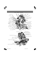
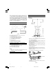
NAME OF PARTS Motor Digital display (only C12LSH) Nameplate Motor head Dust bag Lever (A) Gear case Handle Locking pin Hinge Spindle cover Washer (B) Holder (A) Clamp lever Rotation direction Sub cover Laser marker Lower guard Knob (B) Indicator (For right bevel scale) Set pin (A) Saw blade Sub fence (A) Fence (A) Sub fence (B) Table insert 5 mm machine screw Turntable Vise assembly Side handle Fence (B) Base Fig.
SPECIFICATIONS Item Motor Model Type Power source Voltage (Volts) Power input Laser Marker Maximum output (lambda) Laser medium Digital Display (Only Model C12LSH) Applicable saw blade No load speed Max. sawing Miter dimension C 12LSH / C 12RSH Series commutator motor Single-phase AC 50Hz (230V, 240V) 1520 W (For New Zealand : 1600 W) Po<3mW CLASS II Laser Product 654 nm Laser Diode Precision ±0.5° Outside Dia. 305 mm Hole Dia. 25.4 mm 4000/min (For New Zealand : 3800/min) Head Turntable Max.
STANDARD ACCESSORIES 1 2 3 PREPARATION BEFORE OPERATION 256 mm Make the following preparations before operating the power tool: 1. Installation 281 mm When cutting the workpiece which has the dimension of “*” there might be some possibility of the lower end of the circular saw to touch with the workpiece, even if the motor head is located at the lower limit position. Pay attention when cutting the workpiece. For further details, refer to “PRACTICAL APPLICATIONS” on page 13.
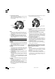
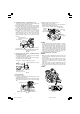
2. Releasing the locking pin When the power tool is prepared for shipping, its main parts are secured by a locking pin. Move the handle slightly so that the locking pin can be disengaged. (2) Next, check that the lower guard returns to the original position when the handle is raised. Lever (A) Handle Handle Locking pin Lower guard Pull Fig. 7 Fig. 6 NOTE Lowering the handle slightly will enable you to disengage the locking pin more easily and safely.
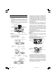
BEFORE CUTTING 1. Cutting a groove on the guard Holder (A) has a guard (see Fig. 8) into which a groove must be cut. Loosen the 6 mm knob bolt to retract the guard slightly. After placing a suitable wooden piece to sit on the fence and the table surfaces, fix it with the vise assembly. After the switch has been turned on and the saw blade has reached maximum speed, slowly lower the handle to cut a groove on the guard.
(1) Turn the 8 mm depth adjustment bolt, change the height where the bolt head and the hinge contacts, and adjust the lower limit position of the saw blade. NOTE Confirm that the saw blade is adjusted so that it will not cut into the turntable. 4.
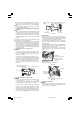
9. Installing the holders ... (Optional accessory) The holders help keep longer workpieces stable and in place during the cutting operation. (1) As indicated in Fig. 14, use a steel square for aligning the upper edge of the holders with the base surface. Loosen the 6 mm wing nut. Turn a height adjustment bolt 6 mm, and adjust the height of the holder. (2) After adjustment, firmly tighten the 6 mm wing nut and fasten the holder with the 6 mm knob bolt (optional accessory).
(1) Light up the laser marker and make a groove of about 5 mm deep on the workpiece that is about 20 mm in height and 150 mm in width. Hold the grooved workpiece by vise as it is and do not move it. For grooving work, refer to “13.Groove cutting procedures” on page 19. Fig. 19 Saw blade Workpiece * * Laser radiation- Do not stare into beam. Laser radiation on work table. Do not stare into beam. If your eye is exposed directly to the laser beam, it can be hurt. * Do not dismantle it.
NOTE Check and make sure on a periodic basis if the position of the laser line is in order. As regards the checking method, draw a right-angle ink line on the workpiece with the height of about 20 mm and the width of 150 mm, and check that the laser line is in line with the ink line [The deviation between the ink line and the laser line should be less than the ink line width (0.5 mm)]. (Fig. 23) 13.
PRACTICAL APPLICATIONS WARNING * To avoid personal injury, never remove or place a workpiece on the table while the tool is being operated. * Never place your limbs inside of the line next to warning sign while the tool is being operated. This may cause hazardous conditions (see Fig. 26). Line Warning sign Warning sign Line Fig. 26 1. Switch operation Pull the trigger to turn on the switch, release it to shut it off.
* Continued cutting operation can result in overload of the motor. Touch the motor and if it's hot, stop your cutting operation once and rest for 10 minutes or so, and then restart your cutting operation. * Do not operate the head section or lift up the main unit while grasping the digital display (Fig. 1) as this could cause damage to the digital display. 4. Cutting narrow workpieces (Press cutting) Slide the hinge down to holder (A), then tighten the slide securing knob (A)/(B) (see Fig.
Loosen Tighten Clamp Lever Clamp lever Pull Knob (B) Holder (A) Indicator Bevel scale Set pin (A) (for right bevel scale) Fig. 33 WARNING When the workpiece is secured on the left or right side of the blade, the short cut-off portion will come to rest on the right or left side of the saw blade. Always turn the power off and let the saw blade stop completely before raising the handle from the workpiece.
(2) Re-tighten the side handle to secure the turntable in the desired position. (3) The miter scale (Fig. 37) indicates both the cutting angle on the angle scale and the gradient on the grade scale. (4) The gradient, which is the ratio of the height to the base of the triangular section to be removed, may be used for setting the miter scale instead of the cutting angle, if desired (see Fig. 37). (5) Therefore, to cut a workpiece at a grade of 2/10, set the indicator to position a as indicated in Fig. 37.
Type of Crown Molding Head To process crown To process crown molding at positions molding at positions 1 and 4 in Fig. 41. 2 and 3 in Fig. 41. Miter Angle Bevel Angle Miter Angle Bevel Angle Setting Setting Setting Setting 45° Type right 35.3° left 30° ( mark) ( mark) left 35.3° ( mark) left 30° ( mark) 38° Type right 31.6° left 33.9° ( mark) ( mark) left 31.6° ( mark) left 33.9° ( mark) Bevel angle scale 3 (1) Setting to cut crown moldings at positions 1 and 4 in Fig. 41 (see Fig.
• • Head Crown molding Stopper (L) Crown molding Stopper (R) Crown molding Crown molding vise ass’y stopper (R) (optional accessories) (optional accessories) 6mm knob bolt 6mm knob bolt Bevel angle scale 4 1 Miter angle scale Turntable Fence (A) Base 6mm wing bolt Crown molding stopper (L) (Optional accessories) Fig. 46 Head Fig.
Position crown molding with its WALL CONTACT EDGE against the guide fence and its CEILING CONTACT EDGE against the crown molding Stoppers as shown in Fig. 50-b. Adjust the crown molding Stoppers according to the size of the crown molding. Tighten the 6mm wing bolt to secure the crown molding Stoppers. Refer to the lower table for the miter angle. Position in Fig.
CAUTION Empty the dust bag frequently to prevent the duct and the lower guard from becoming clogged. Sawdust will accumulate more quickly than normal during bevel cutting. Washer (B) Tighten Loosen SAW BLADE MOUNTING AND DISMOUNTING 1. Mounting the saw blade (Fig. 55-a, Fig. 55-b, Fig. 55c and Fig. 55-d) (1) Use the Phillips screwdriver to loosen the 5 mm screw fastening the spindle cover and then turn the spindle cover.
MAINTENANCE AND INSPECTION WARNING To avoid an accident or personal injury, always confirm that the trigger switch is turned OFF and the power plug has been disconnected from the receptacle before performing any maintenance or inspection of this tool. 1. Inspecting the saw blade Always replace the saw blade immediately upon the first sign of deterioration or damage. A damaged saw blade can cause personal injury and a worn saw blade can cause ineffective operation and possible overload to the motor.
SERVICE AND REPAIRS All quality power tools will eventually require servicing or replacement of parts because of wear from normal use. To assure that only authorized replacement parts will be used and that the double insulation system will be protected, all service (other than routine maintenance) must be performed by an AUTHORIZED HITACHI POWER TOOL REPAIR CENTER ONLY. NOTE Specifications are subject to change without any obligation on the part of HITACHI.
03Eng_C12LSH_Eng 23 4/26/07, 5:33 PM ITEM NO. 1 2 3 4 5 6 7B 8 9 10 11 12 13 14 15 16A 17 18 19 20 21 22 23 24 25 26 27 28 29 30 31 32 33 34 35A 36 37 38 39 40 41 42 43 44 45A 47 48 49 50 51 52 53 54 55 56 57 58 59 60 61 62 63 PART NAME MACHINE SCREW M4 × 12 BOLT WASHER M4 COVER (B) MACHINE SCREW (W/SP. WASHER) M5 × 16 SUPPORT (E) HOLDER SHAFT NEEDLE D5 × 19.8 GEAR (A) SEAL LOCK HEX.
03Eng_C12LSH_Eng 24 4/26/07, 5:33 PM ITEM NO. 131 132 133 134 135 136 137 138 139 140 141 142 143 144 145 146 147 148 149 150 151 152 153 154 156A 157 158 159 160 161 162 163 164 165 166 167 168 169 170 171 173 174 175 PART NAME MACHINE SCREW M4 × 12 BOLT WASHER M4 NYLON CLIP SUPPORT HEX.
03Eng_C12LSH_Eng 25 4/26/07, 5:33 PM ITEM NO. 231 232 233 234 235 236 237 238 239 240 241 242 243 244 245 247 248 249 250 251 252 253 254 255 256 257 258 259 260 261 262 263 264 265 266 267 268 269 270 271 272 273 274 275 276 277 278 279 280 281 PART NAME HANDLE (L) TAPPING SCREW (W/FLANGE) D5 × 25 SWITCHING POWER SUPPLY TAPPING SCREW (W/FLANGE) D4 × 16 CORD INTERNAL WIRE (B) CORD BUSH HANDLE (R) CORD ARMOR D10.
03Eng_C12LSH_Eng 26 4/26/07, 5:33 PM ITEM NO. 6 17 19 20 21 22 23 24 25 26 27 28 32 33 34 37 38 39 40 41 42 43 44 45A 47 48 49 50 51 53 54 55 58 59 60 61 62 63 64 65 66 67 68 69 70 71 72 73 74 75 PART NAME HOLDER SHAFT NYLOCK HEX. SOCKET SET SCREW M8 × 16 GEAR (A) FLAT HD.
03Eng_C12LSH_Eng 27 4/26/07, 5:33 PM ITEM NO. 131 132 133 134 135 139 140 141 142 143 144 145 146 147 148 149 150 151 152 153 154 156A 157 158 159 160 161 162 163 164 165 166 173 174 175 179 180 181 182 183 184 185 186 PART NAME MACHINE SCREW M4 × 12 BOLT WASHER M4 NYLON CLIP SUPPORT HEX. SOCKET SET SCREW M8 × 10 MACHINE SCREW (W/WASHERS) M5 × 16 SIDE COVER MACHINE SCREW M4 × 8 BOLT WASHER M4 BUSHING BALL BUSHING HOLDER (A) KNOB BOLT M6 × 25 LOCK SPRING SEAL LOCK HEX.
03Eng_C12LSH_Eng 28 4/26/07, 5:33 PM ITEM NO. 231 232 233 234 235 237 238 239 240 241 242 243 244 245 247 248 249 250 251 252 253 254 255 256 257 258 259 262 263 264 265 266 267 268 269 270 271 272 273 274 275 276 277 278 279 280 281 282 283 PART NAME HANDLE (L) TAPPING SCREW (W/FLANGE) D5 × 25 SWITCHING POWER SUPPLY TAPPING SCREW (W/FLANGE) D4 × 16 CORD CORD BUSH HANDLE (R) CORD ARMOR D10.
03Eng_C12LSH_Eng 29 4/26/07, 5:33 PM
03Eng_C12LSH_Eng 30 4/26/07, 5:33 PM
03Eng_C12LSH_Eng 31 4/26/07, 5:33 PM
Hitachi Koki Co., Ltd. 705 Code No.