VTL4024E Instruction manual Manuale di istruzioni To obtain the best performance and ensure years of trouble-free use, please read this instruction manual completely. Per garantire la migliore prestazione e la più lunga durata leggere attentamente e al completo le seguenti istruzioni. Bedienungsanleitung Manual de instrucciones Bitte lesen Sie diese Bedienungsanleitung aufmerksam durch, um durch richtige Bedienung jahrelangen und störungsfreien Betrieb zu gewährleisten.
ENGLISH WARNING PRECAUTIONS • Main supply: AC 230V, 50 Hz only • Do not remove panel covers by unscrewing them. There are no user-serviceable parts inside. Refer all servicing to qualified service personnel. • To prevent fire or shock hazard, do not expose this unit to rain or moisture. Safety • Should any solid object or liquid fall into the cabinet, turn off the unit and have it checked by qualified personnel before operating it any further. • To disconnect the mains lead, pull it out by the plug.
CONTENTS Recording • Three Touch-Selectable Recording Speeds (03, 12, 24) • Recording Check • Auto Recording Check • On-Screen and On-Tape Time/Date Information • 7-Day Programmable On/Off Timer • “Alarm On” Output • Usable Audio at 03, A12 and A24 hour Speeds CONTROLS AND FUNCTIONS ..................................3 INSTALLATION ...........................................................7 EXTERNAL CONNECTIONS.......................................8 CASSETTE TAPES ........................................
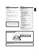
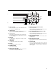
CONTROLS AND FUNCTIONS ENGLISH [FRONT] 8 34 5 6 7 1 2 S 9 1011 12 13 14 1516 DISPLAY (See page 5) 1. SLOW TRACKING CONTROL Adjust to optimize the picture quality in the SLOW PLAY mode, e.g. 24 hours speed. 2. TRACKING CONTROL Adjust to optimize the picture quality during playback at the 03, A12 and A24 hour speeds. 10. RESET BUTTONS Press these buttons at the same time to clear all (microprocessor) functions. Press the “S” button to reset the system. (This does not erase the stored information.
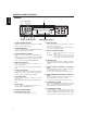
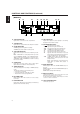
19 18 ENGLISH 17 29 28 27 20 21 22 17. EJECT BUTTON Press to remove the cassette. The EJECT button will not operate in the RECORD mode. 23 24 25 26 25. REWIND/VISUAL SEARCH BUTTON Press to start rewind. Press this button during playback and a reverse playback picture at high speed can be seen. 18. STOP BUTTON Press to stop the tape. The STOP button must be pressed to end the RECORD and PLAY mode. 19. PLAY BUTTON Press to play recorded material in the forward direction.
ENGLISH CONTROLS AND FUNCTIONS (Continued) [DISPLAY] 30 31 32 33 TAB ALARM TAPE END REC 39 INDEX 34 35 37 38 36 LOCK A HARD SOFT SPEED TIMER 40 30. TAPE-IN INDICATOR Lights when a cassette is in the compartment. 41 42 38. SOFT INDICATOR Lights when adjust the picture quality to soft during playback mode and after setting. 31. TAB INDICATOR Lights when a cassette without its safety tab is loaded. 32. ALARM INDICATOR ALARM appears during alarm recording.
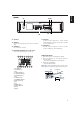
44 45 43 46 43. AC INLET ENGLISH [REAR] 47 48 47. AUDIO IN 44. VIDEO IN Receives video signal from a video camera or another VCR. Accepts an audio signal from a camera, external sound equipment or another recorder (Line: –8 dBm, 50 kohm, unbalanced). 48. AUDIO OUT 45. VIDEO OUT For connection to monitor. Provides an audio output for a monitor or another recorder (–9 dBm, 600 ohm, unbalanced). 46. EXTERNAL INTERFACE (8 X 2-PIN) JACK Connect an alarm switch, door sensor, etc.
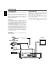
ENGLISH INSTALLATION VIDEO CONNECTIONS Use coaxial cables when connecting a camera and a monitor to this VCR. Note: Long cable runs to distant cameras may cause signal deterioration and/or sync discrepancies. If these problems occur, use video line amplifiers and/or cameras having phase-adjustable line-locked vertical sync. Video Input In single camera systems, connect the camera to the Video IN BNC terminal on the VCR rear panel.
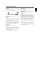
ALARM IN You can connect an alarm switch with a resistance of 1 kohm or less or a door sensor. Connect pin q to !5 or !6 (ground) through the switches. ALARM IN 1 GND 15 or 16 Note: Do not apply a voltage to pin q , !5 or !6. ALARM OUT Approx. 12V is applied to pin w during an alarm recording. Notes: • When you have selected “PULSE” in the “ALARM OUT” menu in the ALARM display, approx. 12V pulses will be applied to the output after the alarm recording ends.
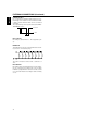
ENGLISH EXTERNAL CONNECTIONS (Continued) CAMERA SW OUT Pin o outputs the following signal each time a onefield image is recorded. You can combine this with a video camera switcher which can be controlled externally. The output timing can be specified using the SELECTION MENU screen. 4.5~5.5V 0~0.4V 5±2 ms REC START IN Recording is started when 5 ~ 12V is applied to pin !0. REMOTE IN This VCR can be remote controlled when the following circuit is connected to pin !3.
TAPE LIFE Slower speed operation in time lapse recording applies stress to video tape. Tapes should be inspected and, if necessary, discarded after the total number of complete tape passes (recording and playback) exceeds the following limits: Tape Speed 03, 12, 24 Complete Tape Passes 50 INSERTING A CASSETTE Note: This is the first step in all VCR operations. The VCR will not operate without a cassette in place.
ENGLISH SETUP On-Screen displays are provided to aid setup of the programmable functions. The seven functions on the Program Menu appear individually on the monitor in this order. 1. TIME/DATE 2. CLOCK SET 3. TIMER 4. SELECTION MENU 1 5. SELECTION MENU 2 6. ALARM 7.
TIME (HOUR, MINUTE, SECOND) DATE (DAY, MONTH, YEAR) DAY OF WEEK: Corrected automatically to C LOCK SET match the input 01– 01–01 MON date. 0 : 00: Notes: • Perform the same procedure as when setting the time and date to make corrections after having set them. The minutes flash on/off when the SET button is pressed (in step 2 above). • To record time and date on the tape, display them on the monitor screen. If they are not displayed on the monitor, they cannot be recorded on the tape.
ENGLISH SETUP (Continued) SETTING [OPTIONS] ITEMS OSD TYPE: You can select the TIME/DATE display from three options: FULL, HALF and OFF. FULL DATE POWER LOSS (IF SENSED) DAY OF WEEK ALARM COUNT* 20– 12– 01 PL THU A00 18 : 15 : 46 03 T L SECURITY LOCK (IF ACTIVATED) TIMER (IF ON) TIME ADJUST: When two or more of this VCR model are connected to pins i TIME ADJUST of each EXTERNAL INTERFACE jack, the clocks in both VCRs can automatically be set to the same time (TIME ADJUST function).
Notes: 1. Programming the TIMER function does not activate it. See TIMER recording, page 19. 2. To record the time and date press the PROGRAM button to display them. 3. When the preset START time is later than the STOP time, the recording will be made into the following day. 4. When the START time and STOP time are the same, a recording will not be made. 5. When the programs for timer recording overlap each other, recording will be switched to the program with the later recording start time.
ENGLISH SETUP (Continued) SETTING THE VCR FUNCTIONS The SELECTION MENU 1 screen allows you to select the VCR operations and functions to match the applications. VIDEO MODE (AUTO, COLOUR, B/W) • Use during recording or playback if the video signal is unstable, etc. AUTO: The unit automatically detects the type of the video input or playback signal and switches to the colour or black-and-white video signal mode, as appropriate. COLOUR: Selects the colour video signal mode.
ENGLISH SETTING THE BUZZER This VCR has a buzzer function. Use SELECTION MENU 2 to select the times when you wish buzzer to sound. Note: “OFF” is specified for all buzzer options at the factory. TAPE END (ON or OFF) • To specify whether buzzer turns on or off, synchronized with pin 4 TAPE END OUT of the EXTERNAL INTERFACE jack. ON: Buzzer will keep sounding when tape reaches the end during recording. OFF: Buzzer will not sound even when tape reaches the end.
ENGLISH SETUP (Continued) SETTING THE ALARM The ALARM function allows the user to set the recording duration, speed to be recorded and tape recycle for alarm recordings. When a contact closure occurs at the ALARM IN input, the VCR automatically enters the RECORD mode at the pre-programmed ALARM recording speed. (See Alarm In, page 8 for a complete description of the ALARM sequence.) The ALARM recording duration can last from 5 seconds to TAPE END, or until the contact closure is reopened.
ENGLISH ALARM MEMORY RECALL AND RESET The VCR signals that an alarm has occurred by flashing the ALARM indicator. If a power loss has occurred, a “PL” will appear in the first line of the TIME/DATE 1 display. ALARM COUNT : Displays the number of alarm inputs that have occurred. Counts up to 99 inputs. A LARM MEMORY A00 1 2 3 4 5 6 7 8 9 ALARM MEMORY: 1: Displays the date/time of the first alarm recording.
ENGLISH OPERATION TAPE RECORDING CAUTION: Recording over existing recorded material will completely erase that material. To prevent accidental recording over the end of a previous recording, advance the tape several seconds before beginning the next recording. 1. Insert a video cassette; be sure the cassette safety tab is intact, or the tab slot is covered. 2. Press the REC/PLAY HOURS button until the desired tape speed is observed on the tape speed indicator. 3. Press the RECORD button to start recording.
MASTER SYSTEM RESET Press the two reset buttons simultaneously to provide a MASTER SYSTEM RESET. Use to reset abnormal displays and operations. The programmable features must be re-programmed. PLAYBACK 1. Rewind the tape to the desired beginning point. (Press the REWIND button, and observe the digital counter until the desired number appears.) Press the stop button. 2. Press the REC/PLAY HOURS button until the desired tape speed is observed on the tape speed indicator. 3.
ENGLISH OPERATION (Continued) VISUAL SEARCH (High Speed Scan) Note: The visual search function allows the recorded material to be reviewed at 3, 5, 7 or 9 times the 03 hour speed mode. 1. Press the PLAY button. 2. Press the SEARCH (F.FWD) button to select the VISUAL SEARCH FORWARD mode, or press the SEARCH (REWIND) button to select the VISUAL SEARCH REVERSE mode. 3. Press the PLAY button again to resume normal playback. Notes: • The visual search speed can be changed using the SELECTION MENU 1 screen.
PROBLEM GUIDE Check these things: ENGLISH If you are having this kind of trouble: ■ No power (No indicators ON) ■ Check to see if unit is plugged in. (Power at supply outlet?) ■ Recorder fails to respond to user command/ operation ■ Perform MASTER SYSTEM RESET. See page 20. ■ No monitor picture ■ Carefully check monitor/VCR/camera connectors. ■ “NO VIDEO” appears on the monitor screen during recording. ■ This will appear when no video signal is input.
ENGLISH SPECIFICATIONS Video Cassette: Recording: Tape Speed: Tape Width: Operation Temperature: Video: Recording Lengths: Video Input: Video Output: S/N Ratio (Video): S/N Ratio (Audio): Horizontal Resolution: Audio Input: Audio Output: Audio Frequency Range: Power: Power Consumption: Cabinet Size: Weight: VHS type Rotary two-head helical scan azimuth recording 23.39 mm/sec. (03 mode) 12.
This table shows the times for maintenance/inspection of each component. Use the table as reference, since the maintenance/inspection times vary depending on the environment where the VCR is used and the way it is used. If the components indicated C/R do not function normally after cleaning, replace them. Please contact the dealer for detail information.
ENGLISH SOME DO’S AND DON’TS ON THE SAFE USE OF EQUIPMENT This equipment has been designed and manufactured to meet international safety standards but, like any electrical equipment, care must be taken if you are to obtain the best results and safety is to be assured. ★★★★★★★★★★ DO read the operating instructions before you attempt to use the equipment.
26 ENGLISH
Hitachi, Ltd. Tokyo, Japan International Sales Division THE HITACHI ATAGO BUILDING, No. 15 –12 Nishi Shinbashi, 2 – Chome, Minato – Ku, Tokyo 105-8430, Japan. Tel: 03 35022111 HITACHI EUROPE LTD, Whitebrook Park Lower Cookham Road Maidenhead Berkshire SL6 8YA UNITED KINGDOM Tel: 01628 643000 Fax: 01628 643400 Email: consumer -service@hitachi-eu.com HITACHI EUROPE S.A. 364 Kifissias Ave. & 1, Delfon Str. 152 33 Chalandri Athens GREECE Tel: 1-6837200 Fax: 1-6835964 Email: service.hellas@hitachi-eu.