
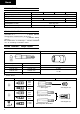
Operation Manual
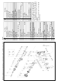

1 Magnetic Hex. Socket
2 Sub Stopper
3 O-Ring (S-16)
4 Locator (A)
5 Lock Sleeve (A)
6 O-Ring (S-28)
7 Fringer (A)
8 O-Ring (F)
9
Tapping Screw (W/Flange)
D4×40
10 Gear Cover Ass'y
11 Set Ring
12 Socket (B) Ass'y
13 Steel Ball D3.175
14 Spring
15 Gear Ass'y
16 Gear Shaft
17 Ball Bearing (608VVMC2EPS2L)
18 Washer (A)
19 Ball Bearing (608VVMC2EPS2L)
20 Second Pinion Ass'y
21 First Gear
22 Washer
23 Inner Cover Ass'y
24 Ball Bearing (608VVMC2EPS2L)
25 Armature
26 Fan Guide (B)
27 Tapping Screw D4×50
28 Stator
29 Housing. Handle Cover Set
30 Name Plate
31
Tapping Screw (W/Flange)
D4×20
32 Speed Control Switch
33 Internal Wire (A)
W8VB
Item
No.
Part time
34 Internal Wire (B)
35 Carbon Brush
36 Brush Holder
37 Hook (A)
38 HITACHI Label
39 Earth Terminal
40 Connector (50091)
41 Internal Wire
42 Noise Suppressor
43 Noise Suppressor
44
Tapping Screw (W/Flange)
D4×16
45 Cord Clip
46 Cord Armor
47 Tube (D)
48 Cord
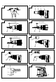
501 + Driver Bit (A) No.2 25L
502 Magnetic Bit Holder
Parts are subject to possible modification
without notice due to improvements.
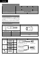
The drawing and the list are parts
structural drawing and parts list of model
W8VB.
For other models refer to the drawing
and the list.
Item
No.
Part time
W8VB The exploded assembly drawing should be used only for authoized service center.