Standard Specifications 1-/3-phase 200V class European Version US Version JP Version Applicable motor size, 4-pole kW(HP) *1 230V Rated capacity 240V Rated output current (A) *2 Overload capacity(output current) Rated output voltage (V) Model X200- Output Ratings 002SFEF2 002NFU2 002LFRF2 0.2(1/4) 0.5 0.5 1.4 004SFEF2 004NFU2 004LFRF2 0.4(1/2) 1.0 1.0 2.6 SFEF2 NFU2/LFUF2/LFRF2 3.1 1.8 5.8 3.4 -SFEF2 -NFU2/LFU2/LFRF2 -LFRF2 -SFEF2 -NFU2/LFU2 -LFRF2 0.8 0.8 0.8 1.0 0.9 0.
Dimensions X200-002SFEF2, NFU2, LFRF2 80(3.15) 80(3.15) 67(2.64) 67(2.64) 5(0.20) 4.4(0.17) 107(4.21) 27(1.06) 2.6(0.10) 2.6(0.10) 13(0.51) Wall 5(0.20) 93(3.66) 5(0.20) 155(6.10) 143(5.63) 155(6.10) Wall 4.4(0.17) 143(5.63) 6(0.24) 6(0.24) 5(0.20) X200-007LFRF2 [Unit: mm(inch)] Inches for reference only X200-004SFEF2, NFU2, LFRF2 X200-005SFEF2 X200-004HFEF2,HFU2, HFRF2 80(3.15) 67(2.64) 5(0.20) X200-007SFEF2,NFU2 110(4.33) 6(0.24) 98(3.86) 189(7.44) 176(6.93) Wall 28(1.
Operation and Programming 1. Setting the maximum output frequency (1) or the value previously monitored is displayed. Power on (2)Function code appears. Press (5) appears. key. (3) appears. Press Press until appears. (6)Preset value is displayed. Press Press (4) until *Pressing 2. Running the motor(by potentiometer) or the value previously monitored is displayed. (8)Returns to and the setting is complete. Press key to store the value.
Operation / Terminal Functions Hardware switches Switch symbol Switch Name SW7 RS-485 communication/key pad selection switch SW7 485 Switch Name Description Select communication connector distination. *1 485 RS-485 communicaiton via Modbus protocol OPE [default] Keypad (option) Select frequency and run command input source. SW8 The SW8 is for the Safety signal input. If you turn this DIP switch ON, the inverter is ready to receive Safety signal from the dedicated terminal #3.
Function List The parameter tables in this chapter have a column titled "Run Mode Edit." An Ex mark x means the parameter cannot be edited; a Check mark means the parameter can be edited. The table example to the right contains two adjacent marks "x ". These two marks (that can also be "xx" or " ") correspond to low-access or high-access levels to Run Mode edits (note Lo and Hi in column heading).
Function List [ X:: Allowed Not allowed ] A Group: Standard functions Function Code PID Control PID Control AVR function Automatic Energy Saving Operation mode and acc./dec. function External freq.
Function List Function Code Others Name b050 b051 b052 b053 b054 b055 b056 b080 b082 b083 Selection of the non stop operation Non stop operarion start voltage setting OV-LAD Stop level of non stop operation setting Deceleration time of non stop operation setting Frequency width of quick deceleration setting DC bus AVR P-gain DC bus AVR I-time [AM] terminal analog meter adjustment Start frequency adjustment Carrier frequency setting b084 Initialization mode (parameters or trip history) b085 b086 b087 b
Function List Allowed [ X:: Not allowed ] H Group: Motor constants functions Function Code Motor constants and gain Name H003 H203 H004 H204 H006 H206 Default Range Motor capacity, 1st motor Motor capacity, 2nd motor Motor poles setting, 1st motor Motor poles setting, 2nd motor Motor stabilization constant, 1st motor Motor stabilization constant, 2nd motor -EF(CE) -U(UL) -R(JP) Factory Factory Factory set set set 4 4 4 4 4 4 100 100 100 100 100 100 0.2/0.4/0.55/0.75/1.1/1.5/2.2/3.0/4.0/5.
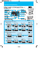
Connecting Diagram Source type logic X200 R(L1) Power source 1-/3-phase 200~240V+10%, -15% 3-phase 380~480V+10%, -15% 50/60Hz 5% (T1) U S(L2) (T2) V T/N(L3) Motor (T3) W DC24V P24 5 (+1)PD DC link choke (+)P 4 Dynamic breaking umit (BRD) ( - )N R1 AL1 R2 AL2 2 AL2 1 AL1 Intelligent relay output contacts AL0 PCS Short bar L DC 0~10V(8bit) AM DC10V H 11 Frequency setting 1k ~2k Current input 4mA~20mA O Intelligent output terminal CM2 OI 10k L 250 Note 1: Common terminals are d
Connecting Diagram Sink type logic : "9#% +")% # *!'+# - :1 : *!'+# / - / :1 : ; < : !"%$ .'% "$"% $# &# $ *)$ $#%, ' + $#%, ' + $(*# !" # ( ', .%#' & ), $ 8 8 8 $# &# $ %# '( ")$*)$ " $' $+ - /.
Wiring and Accessories Power Supply Input Voltage Applicable Motor (kW(HP)) Fuse (Class J) X200-002LFRF2 16 1.25 10 X200-004NFU2/SFEF2 14 2.0 10 X200-004LFRF2 16 1.25 10 0.55(3/4) X200-005SFEF2 14 2.0 10 0.75(1) X200-007NFU2/SFEF2/LFRF2 14 2.0 1.1(1.5) X200-011SFEF2 10 5.5 X200-015NFU2/SFEF2 10 5.5 X200-015LFRF2 14 2.0 X200-022NFU2/SFEF2 10 5.5 30 X200-022LFRF2 14 2.0 30 3.7(5) X200-037LFU2/LFRF2 12 3.5 30 5.5(7.5) X200-055LFU2/LFRF2 10 5.3 40 7.
Torque characteristics/Derating Curves Torque characteristics Base frequency = 60Hz Base frequency = 50Hz Short time performance Short time performance 150 150 0.2~4kW 130 Output torque (%) Output torque (%) 130 Continuous performance 100 95 5.5, 7.5kW 80 100 90 Continuous performance 0.2~4kW 5.5, 7.5kW 75 55 0.2~4kW 55 45 45 35 0.2~4kW 35 5.5, 7.5kW 5.5, 7.5kW 1 6 20 60 120 1 5 16.
For Correct Operation Application to Motors Application to general-purpose motors Operating frequency The overspeed endurance of a general-purpose motor is 120% of the rated speed for 2 minutes (JIS C4,004). For operation at higher than 60Hz, it is required to examine the allowable torque of the motor, useful life of bearings, noise, vibration, etc. In this case, be sure to consult the motor manufacturer as the maximum allowable rpm differs depending on the motor capacity, etc.
For Correct Operation Main power supply Installation of an AC reactor on the input side In the following examples involving a general-purpose inverter, a large peak current flows on the main power supply side, and is able to destroy the converter module. Where such situations are foreseen or the connected equipment must be highly reliable, install an AC reactor between the power supply and the inverter. Also, where influence of indirect lightning strike is possible, install a lightning conductor.
MEMO 17
MEMO 18