
Brochure


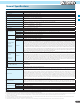


10
Short bar
Short bar
2 1 L PLC P24
2 1 L PLC P24
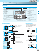
Terminal Arrangement and Screw Diameter
Terminal Description
Terminal Arrangement of Control Circuit Terminals
Wiring sample of control logic terminal (Sink logic)
RS-485
comm.
Logic inputs
Logic common
and power supply
Relay contacts
RS-485
comm.
Pulse
Train
output
Pulse
Train
input
Analog input Analog output Logic outputs
Short bar
SN
SP
AL2 AL1 AL0
EO EA H O OI L AM CM2 12 11
7 6 5 4 3 2 1 L PLC P24
Sink logic
Source logic
Sink / source logic of intelligent input terminals
Symbol Terminal Name
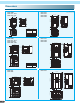
R/L1, S/L2, T/L3 Main power supply input terminals
U/T1, V/T2, W/T3 Inverter output terminals
PD/+1, P/+ DC reactor connection terminals
Terminal (
Arrangements / Functions
)
Symbol Terminal Name
P/+, RB External braking resistor connection terminals
P/+, N/- External braking unit connection terminals
G Ground connection terminal
Terminal Model
Screw Diameter
004MF
001 – 004SF
001 – 007LF
M3.5
007MF
007– 022SF
015 – 037LF
004 – 040HF
M4
Power input Output to motor
Terminal Model
Screw Diameter
055 – 075LF
055 – 075HF
M5
150LF M8
110LF
110 –150HF
M6
Power input Output to motor
RB
PD/+1
P/+ N/-
R/L1 S/L2 T/L3 U/T1 V/T2 W/T3
T/L3 U/T1 V/T2 W/T3
PD/+ P/+
R/L1 S/L2
N/-
RB G G
Sink or source logic is switched by a short bar as below.
Short bar
(Sink logic)
SN 7 6 5 4 3 2 1 L PLC P24
SP EO EA H O OI L AM CM2 12 11
RYRY
Variable resistor
for freq. settting
(1kΩ –2kΩ)
Freq. meter
(27Vdc 50mA max.)