
Instruction Manual Inverter X200 Series


ModBus Data Listing
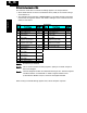
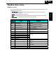
ModBus Coil List
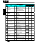
The following tables list the primary coils for the inverter interface to the network. The
table legend is given below.
• Coil Number - The network
register address offset
for the coil. The coil data is a
single bit (binary) value.
• Name - The functional name of the coil
• R/W - The read-only (R) or read-write (R/W) access permitted to the inverter data
• Description - The meaning of each of the states of the coils
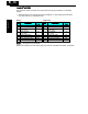
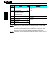
List of Coil Numbers
Coil
Number
Name R/W Description
0000h (Reserved) R
−
0001h Run command R/W 0…Stop
1…Run (enable when A003=03)
0002h FW/RV command R/W 0…RV
1…FW (enable when A003=03)
0003h External trip (EXT) R/W 0…No trip event
1…Trip occurred
0004h Trip reset (RS) R/W 0…No reset condition
1…Reset
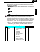
0005h (Reserved) R
−
0006h (Reserved) R
−
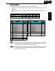
0007h Intelligent input terminal 1 R/W
0008h Intelligent input terminal 2 R/W
0009h Intelligent input terminal 3 R/W
000Ah Intelligent input terminal 4 R/W
000Bh Intelligent input terminal 5 R/W
0…OFF *1
1…ON
000Dh (Not used)
−−
000Eh Run/Stop status R 0…Stop (corresponds to D003 monitor)
1…Run
000Fh FW/RV status R 0…FW
1…RV
0010h Inverter ready R 0…Not ready
1…Ready
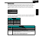
0011h (Reserved) R
−
0012h (Reserved) R
−
0013h (Reserved) R
−
B
−
19
Appendix B