
Instruction Manual Inverter X200 Series

Torque and Constant Volts/Hertz Operation
In the past, AC variable speed drives used an
open loop (scalar) technique to control speed.
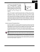
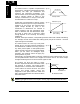
The constant-volts-hertz operation
maintains a constant ratio between the
applied voltage and the applied frequency.
With these conditions, AC induction motors
inherently delivered constant torque across
the operating speed range. For some
applications, this scalar technique was
adequate.
Today, with the advent of sophisticated microprocessors and digital signal processors
(DSPs), it is possible to control the speed and torque of AC induction motors with
unprecedented accuracy. The X200 utilizes these devices to perform complex
mathematical calculations required to achieve superior performance. You can choose
various torque curves to fit the needs of your application. Constant torque applies the
same torque level across the frequency (speed) range.
Variable torque
, also called
reduced torque
, lowers the torque delivered at mid-level frequencies. A torque boost
setting will add additionally torque in the lower half of the frequency range for the
constant and variable torque curves. With the
free-setting torque
curve feature, you can
specify a series of data points that will define a custom torque curve to fit your
application.
Inverter Input and Three-phase Power
The Hitachi X200 Series of inverters includes two sub-groups: the 200V class and the
400V class inverters. The drive describes in this manual may be used in either the
United States or Europe, although the exact voltage level for commercial power may be
slightly different from country to country. Accordingly, a 200V class inverter requires
(nominal) 200 to 240VAC, and 400V class inverter requires from 380 to 480VAC.
For 200V class inverters having a suffix of –SFE accepts single phase 200V class input
voltage, and three-phase for –LFU. All 400V class inverters require three-phase power
supply.
TIP: If your application only has single phase power available, refer to X200 inverter of
3HP or less (European version with a suffix of -SFE); they can accept single phase input
power.
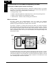
The common technology for single phase power is line (L) and Neutral (N). Three-phase
power connections are usually labeled Line 1 [R/L1], Line 2 [S/L2] and Line 3 [T/L3]. In
any case, the power source should include an earth ground connection. That ground
connection will need to connect to the inverter chassis and to the motor frame (see “Wire
the Inverter Output to Motor” on page 2-21).
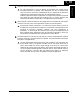
Output
voltage
V
0
Output frequency
100%
f
Constant torque
1
−
13
Getting started