
Instruction Manual Inverter X200 Series


Terminal Dimensions and Torque Specs
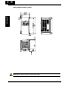
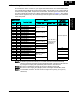
The terminal screw dimensions for all X200 inverters are listed in table below. This
information is useful in sizing spade lug or ring lug connectors for wire terminations.
WARNING: Fasten the screws with the specified fastening torque in the table below.
Check for any loosening of screws. Otherwise, there is the danger of fire.
Models 002S~004S,
002N~004N
Models 007S~022S,
007N~022N,037L,
004H~040H
Connector
Number
of Screw
Terminals
Screw
Diameter
Width
(mm)
Screw
Diameter
Width
(mm)
Power Terminals
(Top side)
5 M3.5 7.1 M4 9.2
8(dual in row)
M3.5 7.1
−−
Power Terminals
(Bottom side)
7
−−
M4 9.2
Control Signal 15 M2
−
M2
−
Alarm Signal 3 M3
−
M3
−
When connecting wiring, use the tightening torque listed in the following table to safely
attach wiring to the connectors.
Screw Tightening Torque Screw Tightening Torque Screw Tightening Torque
M2
0.2N•m (max. 0.25 N•m)
M3.5
0.8N•m (max. 0.9 N•m)
M5
2.0N•m (max. 2.2 N•m)
M3
0.5N•m (max. 0.6 N•m)
M4
1.2N•m (max. 1.3 N•m) −−
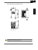
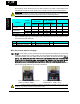
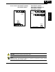
Wire the Inverter Input to a Supply
Step 6: In this step, you will connect wiring to the input of the inverter. First, you must
determine whether the inverter model you have required three-phase power only, or
single-phase power only. All models have the same power connection terminals [R/L1],
[S/L2], and [T/L3]. So you must refer to the specifications label (on the side of the
inverter) for the acceptable power source types! For inverters that can accept single-
phase power and are connected that way, terminal [S/L2] will remain unconnected.
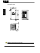
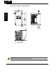
The wiring example to the right shows an X200 inverter wired for 3-phase input. Note
the use of ring lug connectors for a secure connection.
CAUTION: Power terminal assignment is different compared to old models such as L100, L200
series, etc,. Pay attention when wiring the power cable
6
Inverter Mounting
and installation
2−20
Input wiring for 3-phase input
(models -NFU, -HFEF, -HFU)
Input wiring for single-phase input
(-SFEF and -NFU models)