
User manual


Operating Instructions - SLIM-STAR FL digi servo
MULTIPLEX Modellsport GmbH & Co.KG • Neuer Weg 2 • D-75223 Niefern-Öschelbronn • www.multiplex-rc.de Page 1 / 3
Instructions: SLIM-STAR FL digi servo # 82 5752 (05-06-13/CHHO) • Errors and omissions excepted. •
¤
MULTIPLEX
! These operating instructions are an integral part of the
product. They contain important information and safety
notes, and should therefore be kept in a safe place at all
times. Be sure to pass them on to the new owner if you ever
dispose of the product.
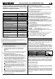
1. SPECIFICATION
SLIM-STAR FL digi servo
Order No. # 6 5386
Type Digital wing-mounting servo
Gearbox Metal
No. of ballraces 2
Multi-wiper potentiometer yes
Case dimensions (L x B x H) 53.7 x 23.5 x 10.3 mm
Installed dimensions incl. frame (L x B x H) 61 x 27 x 11 mm
Weight (incl. mount components)
frame / clip
23 g (27 g)
Operating voltage 4.0 – 7.0 V
Cell count
4 – 5 (NiCd or NiMH)
Transit speed at 4.8 / 6.0 V
1
0.10 / 0.09 s (40q)
Torque at 4.8 / 6.0 V
1
29 / 36 Ncm
Holding power at 4.8 / 6.0 V
1, 2
50 / 60 Ncm
Angular travel
(UNI signal format)
3
r 30q
at 1.5 r 0.5 ms
Max. working range
approx. r 36q
1.5 r 0.60 ms
1
Voltage-stabilized:
4.8 V 4 cells (NiCd or NiMH), 6 V 5 cells (NiCd or NiMH)
2
Angular error < 5q
3
All MULTIPLEX digi-servos with UNI connectors are set up for the UNI signal format. Other
makes of radio control transmitter generally use the UNI signal format. MULTIPLEX RC
transmitters such as the COCKPIT MM, ROYAL evo and PROFI mc 4000 can be switched
between the UNI and MPX servo signal format.
2. SAFETY NOTES
! Please read these instructions before using the servo.
! Regular checks
Check your servos regularly for lost motion, changes to the running
sounds, power and transit speed. If you notice any change, please
ask your model shop or MULTIPLEX Service Centre to check them
for you.
Note:
When the servo is under load you will hear humming and whistling
sounds. This is typical of all digital servos, and does not indicate any
defect.
! Do not overload or stall the servo
Digital servos excel in their precision of movement and great holding
power. In contrast to conventional servos with analogue electronics,
commands are constantly passed to the motor of a digital servo. The
servo attempts to move to the commanded position and maintain it
under all circumstances. Where loads are severe, this results in very
high current drain, and in the long-term this can result in overloading
and even servo failure. For this reason the following points must be
observed when using digital servos, to ensure that its effective life is
as long as possible, and to minimise the risk of failure:
Î Ensure that the control linkage is free-moving. From time to time
disconnect the linkage from the servo and check by hand that the
system still works smoothly and easily. This reduces current drain
considerably, and also helps to ensure accurate positioning.
Î Avoid any situation in which the servo is constantly working
against a force.
Î Digital servos must not be stalled for more than the briefest
moment.
Î If the travel of a control surface is excessive, do not correct it by
reducing servo travel at the transmitter, but by re-connecting the
linkage inward on the servo output arm (or outward at the horn). This
exploits servo torque more effectively, and at the same time reduces
the power required of the servo, and therefore its current drain.
! Note: 5-cell operation
With a 5-cell battery the current drain is higher for a given load, and
this significantly increases the risk of overload and failure.
If you are using 5 cells, it is even more important to observe the
safety notes outlined above.
! Internal mechanical stops
It is essential to ensure that the servos cannot strike their own
internal mechanical end-stops in any operational state (internal
mechanical end-stop at around +/- 36q). This may occur, for example,
if you increase servo travel at the transmitter.
! Do not move the output arm by hand,
as you could cause damage to the servo due to its extremely
compact construction and high-reduction, multi-stage gearbox (use
the RC system or a servo tester, e.g. MULTIPLEX SERVO-MASTER
# 8 2093). Be careful when storing and transporting the model: all
control surfaces should be secured to avoid straining the servos.
! Use separation filters
The SLIM-STAR FL digi servo is specially designed for installation in
wings. This means that extension leads are generally required to
connect them to the receiver. If the extension is longer than 50 cm, a
separation filter must be used, e.g.:
# 8 5035 Separation filter lead (UNI)
# 8 5131 Ferrite ring for separation filter, pack of 5
If you are using ferrite rings (e.g. # 8 5131) note that the cable must
be looped 6 - 8 times through the ring (max. 10 cm from the receiver).
! Protect the servo from vibration
SLIM-STAR FL digi servos are specially designed for installation in
the wings of gliders and electric models. If you wish to use them in
power models (internal combustion engines), effective measures
must be taken to protect them from vibration.
! Ensure that the power supply has adequate capacity (Î 3.2.)
3. USING THE SERVO FOR THE FIRST TIME
1. Connecting the servo
The SLIM-STAR FL digi is not fitted with a receiver lead like conven-
tional servos; instead it features an integral micro socket. The advantage
of this arrangement is that it eliminates problems accommodating cables
and connectors inside cramped wings.
The SLIM-STAR FL digi is supplied with a short lead which allows you to
operate the servo. The lead features a micro-connector on one end, and
a universal UNI connector at the receiver end. The micro-connector is
polarised (pin-outs: see wiring diagram on servo). When connecting the
UNI connector please check the pin assignment beforehand:
Pin assignment: UNI connector
Negative terminal ()
black (brown)
Positive terminal (+) red
Signal ( ) yellow (orange)
When the servo is installed in a wing, the standard connecting lead is
usually not long enough. A 1 m long cable (conductor cross-section 0.13
mm
2
) is available under Order No. # 8 5054. This is suitable for making
your own leads, and features bare wires at the receiver end. If you need
a longer lead, note the following minimum conductor cross-sections:
up to 1.00 m: min. 0.13 mm
2
up to 2.00 m: min. 0.25 mm
2
up to 3.00 m: min. 0.33 mm
2
The standard lead with the micro-connector should then be cut down to a
length of a few centimetres, then extended by soldering to a cable with
the minimum cross-sectional area stated above.
Soldered joints must be carried out competently in order to avoid any risk.
Use only acid-free electronic grade solder flux, and insulate each joint
individually with a heat-shrink sleeve. If you are not confident at
soldering, ask a more experienced modeller to help you.