Kit Best.-Nr. 21 4260 RR Best.-Nr. 26 4260 D GB F I ES Bauanleitung Building instructions Notice de construction Instruzioni di montaggio Instrucciones de montaje 03 12 20 38 46 Ersatzteile Replacement parts Pièces de rechanges Parti di ricambio Repuestos 54 ... 55 © Copyright by MULTIPLEX 2011 ... ... ... ... ... 10 19 37 45 53 Version 1.
Sicherheitshinweise Prüfen Sie vor jedem Start den festen Sitz des Motors und der Luftschraube - insbesondere nach dem Transport, härteren Landungen sowie Abstürzen. Prüfen Sie ebenfalls vor jedem Start den festen Sitz und die richtige Position der Tragflächen auf dem Rumpf. Akku erst einstecken, wenn Ihr Sender eingeschaltet ist und Sie sicher sind, dass das Bedienelement für die Motorsteuerung auf "AUS" steht. Im startbereiten Zustand nicht in den Bereich der Luftschraube greifen.
D Best.-Nr. 21 4260 Machen Sie sich mit dem Bausatz vertraut! MULTIPLEX – Modellbaukästen unterliegen während der Produktion einer ständigen Materialkontrolle. Wir hoffen, dass Sie mit dem Baukasteninhalt zufrieden sind. Wir bitten Sie jedoch, alle Teile (nach Stückliste) vor Verwendung zu prüfen, da bearbeitete Teile vom Umtausch ausgeschlossen sind. Sollte ein Bauteil einmal nicht in Ordnung sein, sind wir nach Überprüfung gern zur Nachbesserung oder zum Umtausch bereit.
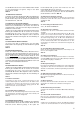
Technische Daten: Spannweite 1366 mm Länge über alles 977 mm Fluggewicht Serie ab 700 g Flächeninhalt ca. 28 dm² (Flügel+Höhenleitwerk, ohne Rumpf) Flächenbelastung ab 25 g/dm² RC-Funktionen Seite-, Höhenruder und Motorsteuerung; Querruder optional Hinweis: Bildseiten aus der Mitte der Bauanleitung heraustrennen! 1. Vor dem Bau Prüfen Sie den Inhalt Ihres Baukastens. Dazu sind die Abb. 1,2+3 und die Stückliste hilfreich. 2.
Sie den Draht in das innerste Loch des Abtriebshebels. Kleben Sie die Bowdenzüge auf ganzer Länge in die dafür vorgesehenen Schlitze. Abb. 16 16. Ruderhörner vorbereiten Schrauben Sie die Inbus-Gewindestifte 24 in die Kardanbolzen 23; 2x für Höhen- und Seitenruder, 4x wenn die Querruder genutzt werden. Klipsen Sie die präparierten Kardanbolzen in die Ruderherhörner „Twin“ 22. 17. Ruderhörner am Leitwerk anbringen Besprühen Sie die Klebeflächen der Ruderhörner mit Aktivator.
55 ein. Die U-Scheibe 59 und die Zahnscheibe 64 werden von der anderen Seite aufgeschoben. Schrauben Sie die M6-Mutter 63 auf den Spannkonus 58. Schieben Sie den Spannkonus 58 auf die Motorwelle und ziehen Sie ihn fest an, bevor der Spinner montiert wird! Abb. 34+35 Ziehen Sie den O-Ring 61 durch den Spinner 56. Abb. 36 Klappen Sie die Luftschraubenblätter 57 nach hinten und führen Sie diese durch den am Spinner seitlich herausragenden O-Ring 61.
41. Vorbereitungen für den Erstflug Für den Erstflug warten Sie einen möglichst windstillen Tag ab. Besonders günstig sind oft die Abendstunden. Vor dem ersten Flug unbedingt einen Reichweitentest durchführen! Halten Sie sich dabei an die Vorgaben des Herstellers Ihrer Fernsteuerung! Sender- und Flugakku sind frisch und vorschriftsmäßig geladen. Vor dem Einschalten des Senders sicherstellen, dass der verwendete Kanal frei ist, sofern eine 2,4 Ghz-Anlage verwendet wird.
Lfd. 1 1.1 2A 2B 3 4 5 6 7 8 9 10 11 12 1 1 1 1 1 1 1 1 1 1 1 1 1 1 Kleinteilesatz 20 3 21 3 22 4 23 4 24 4 25 1 26 2 27 2 28 2 29 2 30 3 Bezeichnung Material Abmessungen Bauanleitung KIT Reklamationsmeldung Modelle Dekorbogen "A" Dekorbogen "B" Rumpfhälfte links Rumpfhälfte rechts m.
Grundlagen am Beispiel eines Flugmodells Ein Flugzeug (egal ob Modell oder „manntragend“) lässt sich mit den Rudern um folgende drei Achsen steuern: Hochachse, Querachse und Längsachse. Die Betätigung des Höhenruders ergibt eine Veränderung der Fluglage um die Querachse (Nicken). Bei Seitenruderausschlag dreht das Modell um die Hochachse (Gieren). Wird Querruder gesteuert, so dreht das Modell um die Längsachse (Rollen). Die Steuerung der Achsen ist für jede Fluglage gültig! Je nach äußeren Einflüssen wie z.
im Gleichgewicht sein. Vor dem Erstflug ist das Einstellen des richtigen Schwerpunkts unbedingt erforderlich. Das Maß wird von der Tragflächenvorderkante (in Rumpfnähe) angegeben. An dieser Stelle mit den Fingern oder besser mit der Schwerpunktwaage MPX # 69 3054 unterstützt soll das Modell waagerecht auspendeln. Abb. B Wenn der Schwerpunkt noch nicht an der richtigen Stelle liegt wird dieser durch Verschieben der Einbaukomponenten (z.B. Antriebsakku) erreicht.
GB Order No. 21 4260 Examine your kit carefully! MULTIPLEX model kits are subject to constant quality checks throughout the production process, and we sincerely hope that you are satisfied with the contents of your kit. However, we would ask you to check all the parts before you start construction, referring to the Parts List, as we cannot exchange components which you have already modified.
Specification: Wingspan 1366 mm Overall length 977 mm Min. all-up weight, standard 700 g Wing area approx. 28 dm² (wing + tailplane, excl. fuselage) Min. wing loading 25 g / dm² RC functions Rudder, elevator and throttle; optional ailerons Note: please remove the pictorial pages in the centre of the building instructions. 1. Before you start building Check the contents of your kit. You will find Figs. 1, 2 + 3 and the Parts List helpful here. 29.
prepared outer sleeves 53, which are 523 mm long. Connect the pre-formed end of the pushrod to the second hole from the outside of the servo output arm. Glue the snake outers in the appropriate channels, running cyano right along the channel. Fig. 16 onto the surfaces which will later make contact with the wing joiner 50. Check that the wing joiner 50 is a snug fit in the wings, but only when you are absolutely confident that there is no active adhesive inside the channel.
shakeproof washer 64 are fitted from the other side. Screw the M6 nut 63 on the taper collet 58. Fit the taper collet 58 on the motor shaft and tighten the nut firmly before fitting the spinner. Fig. 34 + 35 Fit the O-ring 61 through the spinner cone 56. Fig. 36 Fold the propeller blades 57 back, and pass them through the ends of the O-ring 61 which project from the sides of the spinner. Take care to avoid the sharp edges of the propeller blades causing damage to the O-ring 61.
41. Pre-flight checks For the first flight wait for a day with as little breeze as possible; the evening hours often offer calmer conditions. It is essential to carry out a range-check before the first flight! Please follow the instructions laid down by your RC system manufacturer. The transmitter battery and flight pack must be fully charged in accordance with the manufacturer’s recommendations.
Part No. Description Material Dimensions 1 1.1 2A 2B 3 4 5 6 7 8 9 10 11 12 1 1 1 1 1 1 1 1 1 1 1 1 1 1 Building instructions, KIT Complaints form, models Decal sheet „A“ Decal sheet „B“ L.H. fuselage shell R.H. fuselage shell, with fin Canopy Tailplane L.H. wing panel R.H. wing panel L.H. joiner channel cover R.H. joiner channel cover L.H. servo well cover R.H.
The basics of model flying Any aircraft - whether model or “man-carrying” - can be controlled around three primary axes: the vertical axis, lateral axis and longitudinal axis. Operating the elevator produces a change in the aeroplane’s flight attitude around the lateral axis (pitch). Giving a rudder command turns the model around the vertical axis (yaw). If you move the aileron stick, the model rotates around the longitudinal axis (roll).
flight battery). If this is not sufficient, the correct quantity of ballast (lead or modelling clay) should be fixed securely to the nose or tail of the fuselage. If the model is tail-heavy, fit the ballast at the fuselage nose; if it is nose-heavy, attach the ballast at the tail end of the fuselage. Neutral point The neutral point of an aircraft is the point at which the aerodynamic forces are in equilibrium.
F Nr. Com. 21 4260 Familiarisez-vous avec le kit d’assemblage! Les kits d’assemblages MULTIPLEX sont soumis pendant la production à des contrôles réguliers du matériel. Nous espérons que le contenu du kit répond à vos espérances. Nous vous prions de vérifier le contenu (suivant la liste des pièces) du kit avant l’assemblage, car les pièces utilisées ne sont pas échangées. Dans le cas où une pièce ne serait pas conforme, nous sommes disposés à la rectifier ou à l’échanger après contrôle.
Données techniques: Envergure 1366 mm Longueur hors tout 977 mm Poids en vol 700 g Surface alaire env. 28 dm² (aile+profondeur, sans fuselage) Charge alaire à partir de 25 g/dm² Fonction RC : direction, profondeur, puissance moteur; ailerons en option Remarque: enlevez les illustrations des pages de milieu de la notice! 1. Avant l’assemblage Vérifiez le contenu de la boite. Pour cela, vous pouvez vous aider de l’image Fig.1,2+3 et de la liste des pièces. 2.
15. Mise en place des gaines de tringles Passez les tringles de commandes métalliques avec embouts en Z pour la gouverne de profondeur et de direction 51 dans la gaine interne 52 (550 mm) puis celle-ci dans la gaine externe de longueur adaptée 53 de 523 mm. Engagez le bout en forme de Z dans le deuxième trou à partir de l’extrémité du palonnier. Collez les gaines extérieures sur la longueur dans les fentes prévue à cet effet. Fig. 16 16.
58. Engagez le cône de fixation 58 sur l’axe moteur et serrez l’ensemble avant de monter le cône! Fig. 34 + 35 Passez le joint torique 61 pardessus le cône 56. Fig. 36 Rabattez les pales d’hélice 57 vers l’arrière et passez-les dans le joint torique 61 dépassant du côté du cône. Veillez à ce que les bords coupants des hélices n’entaillent pas le joint torique 61. Fixez le cône sur l’entraîneur d’hélice 55 à l’aide des deux vis tôle 60. Fig. 37 34.
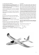
6 8 11 12 7 10 4 9 5 3 Abb. 01 26 24 23 44 22 45 47 46 63 20 3x 64 48 59 21 3x 60 58 62 56 53 61 55 29 25 40 52 57 51 50 43 28 27 30 41 42 Abb.
52 (Ø2/1mm) 53 (Ø3/2mm) Abb. 03 4 31mm (53) 44 45 4 46 Abb. 04 Abb. 05 4 48 Abb.06 Ø3 63 /2 x 5m Ø3/2 x 2 Ø3/2 x 24 m Abb. 07 47mm 7mm 3 4 26 Ø3/2 x 290m m Abb. 08 Abb.
29 29 Abb. 10 Abb. 11 10 43 Abb. 12 Abb. 13 Abb.14 Abb. 15 4 51+ 52+ 53 22+23+24 Abb. 16 Abb.
22+23+24 6 6 47 Abb. 19 Abb. 18 Abb. 20 Abb. 21 11 Abb. 23 Abb. 22 10 22+23+24 8 28 Abb. 24 7+8 Abb.
26 Abb. 26 Abb. 27 18mm (53) 40 Abb. 28 Abb. 29 Abb. 30 Abb. 31 42 30 41 62 30 57 55 30 57 Abb. 32 62 Abb.
58 59 64 63 Abb. 35 Abb. 34 56 60 60 56 61 Abb. 37 Abb. 36 28 28 5 5 Abb. 38 Abb. 39 Abb. 40 Abb.
78 mm Abb. A Abb. B Abb. C Abb. D EASY STAR II Abb.
EASY STAR II Abb. F EASY STAR II Abb. G EASY STAR II Abb.
point. Lorsque vous aurez trouvé cette position, faite un marquage de telle manière a toujours placé l’accu au même endroit. Fig. B 41. Préparatifs pour le premier vol Il est conseillé d’effectuer le premier vol par une météo sans vent. Pour cela, les occasions se présentent souvent en soirée.
Nr. Qt. Désignation Matière Dimensions 1 1.
Bases du pilotage avec un modèle réduit comme exemple Un avion (aussi bien réel ou modèle réduit) se pilote avec les gouvernes suivant 3 axes : l’axe longitudinal, l’axe latéral et l’axe vertical. Une action sur la commande de profondeur conduit à une modification de la position de vol autour de l’axe latéral (Nick). Une action sur la gouverne de direction conduit à une modification de la position de l’appareil autour de son axe vertical (Gier).
Si le centrage correct n’a pas encore été atteint, celui-ci peut l’être en déplaçant les éléments de réception (par ex. l’accu de propulsion). Si cela ne suffit toujours pas, rajoutez du plomb soit à l’avant, dans le nez du fuselage ou à l’arrière, en le fixant correctement. Si le modèle a tendance à basculer sur l’arrière, rajoutez du plomb à l’avant, si c’est l’inverse, rajoutez du plomb à l’arrière.
I Referencia 21 4260 Familiarizzate con la scatola di montaggio! La scatole di montaggio MULTIPLEX vengono sottoposte di continuo ad un controllo del materiale durante la produzione. Speriamo che siate soddisfatti del contenuto della scatola di montaggio. Vi preghiamo, però, di controllare tutte le parti (in base alla lista di pezzi) prima dell’utilizzo, visto che le parti già lavorate non possono essere sostituite.
Dati tecnici: Apertura alare 1366 mm Lunghezza complessiva 977 mm Peso in ordine di volo serie a partire da 700 g Superficie alare ca. 28 dm² (ala+impennaggio elevatore, senza fusoliera) Carico alare a partire da 25 g/dm² Funzioni RC direzionale, elevatore e comando motore; alettoni opzionali Nota: staccare le pagine contenenti le figure dal centro delle istruzioni per il montaggio! 1. Prima del montaggio Controllare il contenuto della scatola. A tal scopo sono d’aiuto le figg. 1,2+3 e la lista pezzi. 2.
tubi interni 52 (550 mm) e quest’ultimi nei tubi esterni tagliati su misura 53 lunghi 523 mm. Appendere il „filo metallico Z“ nel 2o foro dall’esterno al braccio del servo. Incollare i tiranti bowden per tutta la lunghezza nelle apposite fessure. Fig. 16 16. Preparare le squadrette per timoni Avvitare i perni di arresto a brugola 24 ai perni cardanici 23; 2x per elevatore e direzionale, 4x quando vengono utilizzati gli alettoni. Premere i perni cardanici preparati nelle squadrette per timoni „Twin“ 22. 17.
Far passere la guarnizione circolare 61 attraverso l’ogiva 56. Fig. 36 Ribaltare le pale dell’elica 57 indietro e farle passare attraverso la guarnizione circolare che sporge di lato all’ogiva 61. Fare attenzione che le eliche a spigoli vivi non danneggino la guarnizione circolare 61 . Con ambedue le viti a testa cilindrica con calotta in lamiera 60 viene avvitata l’ogiva al mozzo portaeliche 55 . Fig. 37 34. Terminare la capottina cabina Incollare i perni di chiusura 28 nei fori della cappottina cabina 5 .
I pacchi batteria della radio e di volo sono stati caricati da poco e in conformità alle prescrizioni. Prima di accendere la radio assicurarsi, che il canale utilizzato sia libero, per quanto venga utilizzato un impianto da 2,4 Ghz. Se alcuni punti non fossero chiari, non decollare. Consegnare tutto l’impianto (con pacco batteria, cavo dell’interruttore, servi) al reparto di assistena tecnica clienti del costruttore dell’apparecchio in modo che venga controllato. 42. Primo volo...
Posizione Designazione Materiale Dimensioni 1 1.
Nozioni basilari prendendo un aeromodello come esempio Un aereo (a prescindere che sia un modello o uno „guidato da uomini“ può essere pilotato grazie i timoni intorno ai seguenti tre assi: assa d’imbardata, asse di beccheggio e asse di rollio. L’azionamento dell’ elevatore fa variare la direzione di volo intorno all’asse trasversale (beccheggio). Nel caso di escursione del direzionale il modello gira intorno all’asse d’imbardata (anticoppia).
Il punto neutro Il punto neutro di un aereo è il punto in cui le forze aereodinamiche sono in equilibrio. Un aereo che vola in modo stabile ha il punto neutro sempre dietro il baricentro. Nel caso di aerei instabili, il baricentro si trova dietro il punto neutro.Tali aerei non sono più comandabili manualmente ed hanno bisogno di un sistema computerizzato per la stabilizzazione e il controllo. L’incidenza Lincidenza indica la differenza in gradi angolari fra la posizione di quota e dell’ala.
ES Referencia 21 4260 ¡Familiarícese con su Kit! Durante la producción, los materiales de los kits MULTIPLEX se someten a continuos controles. Esperamos que el contenido del kit sea de su agrado.
Características técnicas: Envergadura 1366 mm. Longitud total 977 mm. Peso de serie a partir de 700 gr. Superficie alar aprox. 28 dm² (Alas+estabilizador horizontal, sin fuselaje) Carga alar desde 25 gr./dm². Funciones RC: Dirección, profundidad y control de motor; Alerones opcionales Nota: ¡Separe el cuadernillo central del manual de instrucciones! 1. Antes de comenzar el montaje Compruebe el contenido de su kit. Le serán muy útiles las Img. 1,2+3 y la lista de partes. 2.
15. Montar las fundas bowden Pase los alambres de acero para los timones de dirección y profundidad con forma de Z 51 por el tubo interior 52 (550 mm.) y este en el tubo exterior 53, cortado anteriormente a un largo de 523 mm. Enganche la varilla con forma de “Z” en el segundo agujero, desde fuera, del brazo del servo. Pegue la funda bowden a todo lo largo de la ranura provista a tal efecto. Img. 16 23. Pegar las tapas del larguero Pegue cuidadosamente las tapas 9 y 10 del larguero en las alas 7 y 8.
Encaje el cono tensor en el adaptador 58 y monte el conjunto en el adaptador de la hélice 55. La arandela 59 y el disco dentado 64 se introducen por el otro lado. Enrosque la tuerca M6 63 en el cono tensor 58. Introduzca el cono tensor 58 en el eje del motor y apriételo, ¡Antes de montar el cono! Img. 34 + 35 Instale la junta tórica 61 en el cono 56. Img. 36 Pliegue las palas de la hélice 57 hacia atrás y llévelas hacia la junta tórica 61 que sobresale lateralmente del cono.
Antes del primer vuelo, ¡Es imprescindible hacer una prueba de alcance! ¡Cíñase para ello a las indicaciones del fabricante de su emisora! La emisora y las baterías del avión han de estar recién y debidamente cargadas. Antes de encender la emisora, asegúrese de que el canal a emplear está libre, a no ser que vaya a utilizar un sistema 2,4 GHz. Si tiene la menor duda, no despegue bajo ningún concepto. Envíe el equipo de radio completo (con baterías, cable con interruptor, servos, etc.
Num. Descripción Material Dimensiones 1 1.1 2A. 2B. 3 4 1 1 1 1 1 1 5 6 7 8 9 10 11 12 1 1 1 1 1 1 1 1 Instrucciones KIT Formulario reclamación modelos Lámina decorativa “A” Lámina adhesiva impresa Lámina decorativa “B” Lámina adhesiva impresa Mitad izquierda del fuselaje Elapor Mitad del fuselaje derecha Elapor con Est. Vert.
Conceptos básicos de un aeromodelo Un avión (da igual si es un aeromodelo o “portador de personas”) se controla con los timones mediante tres ejes: Eje vertical, eje transversal y eje longitudinal. La activación del timón de profundidad produce una modificación de la altitud de vuelo sobre el eje transversal (cabeceo). Al mover el timón de dirección, el modelo gira sobre su eje vertical (giro). Al accionar los alerones, el modelo gira sobre su eje longitudinal (alabeo).
componentes (P. Ej., de la batería principal). Si esto no fuese suficiente, se fija y asegura la cantidad adecuada de lastre (plomo o plastilina) en la punta del morro o en la cola del fuselaje. Si el modelo es pesado de cola, el lastre se añadirá en el morro del fuselaje - si el modelo es pesado de morro, se añadirá el lastre a la cola del fuselaje. Punto neutro En un avión, el punto neutro es la posición en la que las fuerzas aerodinámicas están en equilibrio.
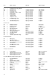
Ersatzteile Replacement parts Pièces de rechanges Parti di ricambio Repuestos # 72 4607 Dekorbogen (zweiteilig) Decal sheet Planche de décoration Decals Lámina decorativa # 22 4239 Rumpfhälften und Bowdenzüge Fuselage shells + snakes Fuselage et tringles Semigusci fusoliera + bowden Mitades fuselajes+bowden # 22 4240 Kabinenhaube Canopy Verrière Capottina Cabina # 22 4241 Höhenleitwerk Tailplane Empennage Impennagio per Kit empenaje # 22 4242 Tragflächen Wings Ailes Ali Alas # 22 4243 Kleinteilesatz Sm
Ersatzteile Replacement parts Pièces de rechanges Parti di ricambio Repuestos Best.-Nr. 21 4260 # 22 4244 Kunststoffteilesatz injected parts Set de pièces en plastique Minuteria in plastica Piezas de plástico # 70 3457 Ruderhorn „Twin“ mit Gestängeanschluss, 2 Satz Horn „Twin“ and pushrod connector, 2 pcs. Guignol „Twin“ raccord de tringles, 2 pcs. Squadretta „Twin“ raccordo per rinvii, 2pz. Escuadra „Twin“ retén de varilla, 2 uds.
MULTIPLEX Modellsport GmbH & Co.KG • Westliche Gewerbestrasse 1 D-75015 Bretten-Gölshausen • www.multiplex-rc.