
Manual
15
shakeproof washer 64 are fitted from the other side. Screw
the M6 nut 63 on the taper collet 58. Fit the taper collet 58 on
the motor shaft and tighten the nut firmly before fitting the
spinner.
Fig. 34 + 35
Fit the O-ring 61 through the spinner cone 56.
Fig. 36
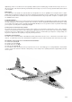
Fold the propeller blades 57 back, and pass them through
the ends of the O-ring 61 which project from the sides of the
spinner. Take care to avoid the sharp edges of the propeller
blades causing damage to the O-ring 61. Fix the spinner to
the propeller boss 55 using the two pan-head self-tapping
screws 60.
Fig. 37
34. Completing the canopy
Glue the latch tongues 28 in the recesses in the canopy 5.
Use thick cyano initially, and fit the canopy on the model
immediately, so that the latch components align themselves
automatically. Wait for at least two minutes before removing
the canopy, then apply drops of thin cyano to the gaps in the
latches to glue them in place, flush with the foam.
Fig. 38 + 39
35. Installing the wings
Slide the wing joiner 50 into one of the wing panels as
shown in the illustration, then fit the joiner through the
fuselage. Before the wing makes contact with the fuselage,
connect the aileron servo lead to the extension lead already
installed in the fuselage. Connect the plug and socket, then
push the wing fully into place; the cable will now form itself
into a loop in the space designed for it. Fit the other wing
panel onto the joiner, and connect the aileron servo lead to
the extension lead already installed in the fuselage, as
described previously.
Fig. 40 + 41
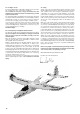
36. Installing the flight battery and receiver
Install the flight pack and receiver in the following arrangement:
the flight battery should be at the extreme nose, the receiver
directly behind it.
Deploy the receiver aerial(s) as described in the RC system
instructions. The aerial tube installed in the underside of the
fuselage is intended for 35 / 40 MHz systems. File a length of
wire to a point, then slip it through the tube from the tail end,
and push the sharpened end into the aerial insulation; a small
drop of cyano will fix the aerial to the wire. The aerial can now
be drawn through the tube to the tail. If you are using a 2.4 GHz
system, cut slits in the foam material (e.g. in the area of the
canopy flange) and press the short aerials into them.
When positioning these components you should bear in mind
the recommended Centre of Gravity (CG) at point 40. Stick the
strips of Velcro tape 20 and 21 (loop side) to the inside of the
fuselage floor. Note that the adhesive on the tape is not
adequate for this application, so fix the tape with cyano for
additional security. The final position of the flight battery is
determined when you check the model’s balance point (Centre
of Gravity - CG). Check that the Velcro tape for the flight battery
is firmly secured. If you neglect this, you could lose your battery
in flight.
Check that the flight pack is secure before every flight!
Temporarily complete all the electrical connections as
described in the RC system instructions.
Do not connect the battery to the speed controller until you
have switched the transmitter on, and are certain that the
throttle control is at the “OFF” position.
Connect the servo leads to the receiver. Switch the transmitter
on, then connect the flight battery in the model to the speed
controller, and the controller to the receiver. This model requires
a BEC-type speed controller (receiver power supply from the
flight battery).
Now switch the motor on briefly, and check once more that the
propeller rotates in the correct direction. If it spins in the reverse
direction, swap over any two of the three motor wires to correct
it. Always hold the model securely when testing the power
system, and remove any loose, lightweight objects before and
behind the model before the propeller does it for you.
Caution: even small motors and propellers are capable of
inflicting injury!
38. Setting the control surface travels
It is important to set the correct control surface travels, otherwise
your model will not respond to your control commands smoothly
and evenly. Up-elevator (stick back, towards you) should be
about 5 mm; down-elevator (stick forward, away from you)
approx. 4 mm. Rudder 10 mm to either side of centre, in
each case measured at the widest part of the control surface.
The ailerons should deflect 8 mm up, and 4 mm down. When
you move the aileron stick to the right, the aileron on the right-
hand wing should deflect up; that on the left-hand wing down.
Please note: when we refer to a model aircraft, the terms “right”
and “left” always apply to the machine when viewed from above,
with the nose pointing away from the observer. If your radio
control system does not include the mixers required to set up
differential aileron travel (as described above), the model will
still fly well with symmetrical (non-differential) travels. If you
are a beginner, you will probably notice no difference in any
case. However, accurate rolling manoeuvres are more difficult
to fly with symmetrical aileron travels. If you cannot set the
recommended travels using your transmitter’s adjustment
facilities, you will have to re-position the pushrod connections,
using different holes at the servo or horn.
39. Finishing the model
The kit includes a multi-colour decal sheet 2 (A + B) for adding
the final touches to the model. Cut out the individual decals
and apply them to the aeroplane in the arrangement shown in
the kit box illustration. The canopy 5 can be coloured black
using a waterproof felt-tip pen. If you wish to apply an all-over
colour scheme, we recommend our range of “ELAPOR® Color”
colour paints, # 60 2701 - # 60 2712 (surfaces must first be
prepared using MULTIPrimer # 60 2700). For tips on painting
our models please refer to the FAQ section on our website.
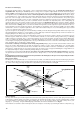
40. Balancing the model
Like every aircraft, your EasyStar II must be balanced correctly
if it is to fly well and stably. To check the Centre of Gravity (CG)
you must first assemble your model completely, ready to fly,
and install the flight battery.
The correct CG is marked at a point about 5 mm from the
rear edge of the wing joiner cover, and the model must
balance at this point. This setting corresponds to about 78
mm aft of the wing root leading edge, measured either side
of the fuselage.
Support the model under both wings on two fingertips at the
marked point, and it should balance level. Minor corrections
can be made by adjusting the position of the flight battery.
Once you have established the correct position for the battery,
mark this in the fuselage to ensure that it is always positioned
correctly.
Fig
. B