
User Manual


26
QUICK START
Be sure to read the Safety Notes before operating the model for the first time.
Depending on the version of the FunCopter you have purchased, you may have to install the electronic components.
MULTIPLEX radio control components for the FunCopter:
RR = Ready for Radio
Tiny S servo 3 x required (roll, pitch-axis, yaw) Order No. 6 5121
or Tiny MG servo 3 x required (roll, pitch-axis, yaw) Order No. 6 5122
MULTIgyro 300DP gyro Order No. 7 5503
MULTIcont BL-37/II speed controller Order No. 7 2276
Gear set Tiny-MG (2x) Order No. 89 3276
RX-6-SYNTH light receiver 35 MHz A/B band Order No. 5 5876
alternatively 40 / 41 MHz Order No. 5 5877
or RX-7-DR light M-Link receiver 2.4 GHz Order No. 5 5810
(only in conjunction with a Multiplex 2.4 GHz transmitter)
Recommended flight battery: Li-BATT FX 3/1-3200 Order No. 15 7371
Li-BATT eco 3/1-3000 Order No. 15 7236
Battery charger:
MULTIcharger LN-3008 EQU Order No. 9 2540
for 2S and 3S LiPo, LiIo and LiFe batteries, also
NiMH and NiCd batteries with four to eight cells
Tools:
Allen keys: 1.5 / 2 / 2.5 / 3 / 4 mm A/F (supplied in the set)
Side-cutters, cross-point screwdriver, slot-head screwdriver (for gyro adjustment), ball-link pliers (recommended).
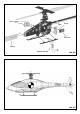
Please refer to the illustration ‘AS’ when installing the electronics. The assembly instructions include a detailed illustration of
the servo installation.
The gyro must be installed with the correct orientation (the right way round); for more information please read the instructions
supplied with the unit. The gyro should be mounted on double-sided foam tape, as this absorbs vibration.
The receiver, speed controller and battery should be attached using Velcro (hook-and-loop) tape. It is important to deploy all
cables in such a way that they cannot foul or become tangled in any moving parts.
It is important to consider the centre of gravity (see Fig. ‘CG’) when installing the flight battery: for hovering the centre of gravity
should be directly below the rotor hub. For higher-speed circuits it is advantageous to position the battery (C.G.) further forward.
The variable pushrods are installed to allow accurate fine-tuning of blade tracking: these make it possible to adjust blade
tracking (i.e. to set both rotor blades rotating in the same horizontal plane), and thereby minimise vibration caused by imperfect
tracking. The illustrations Fig. MR-05 and MR-06 in the pictorial instructions show the variable pushrods (13 + 14) which are
used to adjust blade tracking. Adjust the pushrod lengths to ensure that there is no stress in the system when the pushrods are
installed. Blade tracking can now be corrected by unscrewing the pushrod on one side, and screwing the pushrod in on the
other side by the same number of turns. This action tilts the rotor yoke, which in turn affects the blade tracking. If you find that
blade tracking is worse after making an alteration, adjust the pushrods again to tilt the rotor yoke in the opposite direction.
GB