
User Manual

4. NEUTRAL SETTING
If the motor begins running, you must set the neutral position of the controller. Make
sure you set the throttle on the transmitter to neutral and the trim lever for throttle in
the middle. Using the supplied tuning wand, insert the wand into the neutral
adjustment hole on the SP-520 controller. Slowly turn the neutral controller
potentiometer one direction or the other until the motor stops, and the red indicator
light on the controller just goes out. This is the correct position for the neutral
adjustment. The motor should now move the wheels in the correct direction when the
red or green indicator light comes “ON” while advancing the throttle stick forward. If
yes, the motor wires were cross connected. Correct it by changing the polarity of the
motor wires in reverse. If no light comes “ON”, correct the direction by using the
reversing switch of the transmitter.
5. HIGH SPEED SETTING
To adjust the high speed setting, again disconnect the motor wires. With the motor
disconnected, give the throttle on the transmitter full throttle position. You should see
a green light on the SP-520 controller. If not, use the tuning wand to adjust the “FULL
POWER” potentiometer until the light comes “ON” when full power is commanded
from the transmitter. To take full advantage of the power band of the SP-520, adjust
the full power setting so that the green light will come only when the very last bit of
throttle is added to the transmitter. This will give you a broad mid-range power band
which allows far better control of the car. You may now reconnect the motor to the car.
6. REVERSE
To use the reverse function of the SP-520 PLUS, simply move the throttle stick or
trigger on your transmitter the opposite direction of full throttle. There will be a very
slight delay before reverse power is applied to the motor from the controller, and this
is to prevent damage to the gears of the car. If you cannot get the reverse speeds to
work, you may have to readjust the throttle position on the transmitter to allow for
additional movement in the reverse direction.
TEMPFET PROTECTION
Your SP-520 controller is protected from overheating by a built in TEMPFET device.
The TEMPFET is designed to prevent the controller from being damaged due to
excessive heat. Some high performance modified motors and running a car in grass,
mud or deep sand can cause the motor to work very hard. This causes overheating to
the motor, controller and batteries. Should you overheat the SP-520, it will
automatically stop the car until the controller cools down. If you should experience
this, you should take the time to find the cause of the car working so hard. This could
be dragging parts, jammed wheels, too tight of a gear mesh, and broken parts. Always
check the car carefully before continuing to run the car. The SP-520 will return to
normal operation in a few minutes.
ALUMINUM HEAT SINK AND SILICON BOOT
In any case where high speed running is done, rough terrain is encountered, or high
powered motors are used, always place the aluminum heatsink on the controller to
assit in cooling the controller. The SP-520 will be more efficient when it runs cooler.
Also, the SP-520 has a silicon heatsink boot which not only helps the heatsink to
attach to the controller, but it also transfers the heat away from the controller and
keeps the MOSFETs separated. Please leave the silicon boot in place at all times.
ADDITIONAL TIPS
1. MONOLITHIC CAPACITORS
Motors on model cars generate static electricity which interfere with radio control
equipment. To prevent this from happening, it is necessary to place at least two (2)
monolithic capacitors to the motor of the car. These are supplied with the SP-520.
Solder one end of a capacitor to the positive (+) pole of the motor endbell and the
other end to metal casing of the motor. With the second capacitor, solder one end to
the negative (-) pole of the motor endbell to the same place on the casing as the first
capacitor.
2. AIR CIRCULATION
You can expect some heat to be felt by the heatsink of the SP-520. This is quite
normal. Because the SP-520 operates more efficient when it is cool, always place the
controller on the car chassis in a position where it will receive plenty of air circulation.
3. POWER LOSS PROTECTION
Although the connectors on the SP-520 are already mounted to the 15 gauge wires,
we recommend that you keep the wires as short as possible to get best results. If you
are capable of soldering these wires, the best connection possible will be to connect
the motor wires directly to the motor, leaving the bullet style motor wire connectors off
completely.
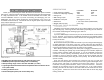
ALTERNATE WIRING AND WIRING DIAGRAM
The SP-520 can be adapted for use with other wire connectors. If you find that you
must change the connectors, please study the wiring diagram carefully. The red wire
is for battery positive (+), the black is battery negative (-), white is motor positive (+)
and blue is motor negative (-). The receiver connector is suitable for use with
FUTABA, JR PROPO, and HITEC systems. When changing connectors, always use
a high grade rosin core solder only, and insulate all connections with heat shrink
tubing. Now, go hit the track and good racing!