TABLE OF CONTENTS INTRODUCTION...................................................................................................... 01 SPECIAL FEATURES............................................................................................. 03 WARNING AND SAFETY NOTES......................................................................... 06 LITHIUM BATTERY CONNECTION DIAGRAM.................................................... 10 PROGRAM FLOW CHART.....................................................
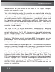
INTRODUCTION Congratulations on your choice of the Hitec X1 MF digital intelligent charger from Hitec RCD USA. This unit is simple to use, but the operation of a sophisticated automatic charger such as the Hitec X1 MF does require some knowledge on behalf of the operator. These operating instructions are designed to ensure that you quickly become familiar with its functions.
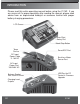
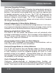
INTRODUCTION Please read this entire operating manual before using the X1 MF. If you are unsure of it’s proper operation after reading the manual, please seek advice from an experienced hobbyist or someone familiar with proper battery charging procedures. LCD Screen Enter/Start Rotary Dial Mode/Stop Button Temp. Sensor DC Input Power Cable 11-18V AC Servo/ESC Port Brushless Motor Sensor Port AC Input Power Port 100-240V AC Balance Socket Port Pitch=2.
SPECIAL FEATURES Optimized Operating Software The Hitec X1 MF features an AUTO function that automatically adjusts the current during charging or discharging operations. Especially for lithium batteries, it can prevent overcharging which may lead to an explosion due to improper parameters set by the user. The X1 MF will disconnect the circuit automatically and produce an audible alarm upon detection of abnormal voltage or current loads.
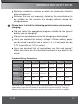
SPECIAL FEATURES Data Store/Load The charger can store up to 10 different charge/discharge profiles for your convenience. Each profile can store settings for battery type and charge/discharge parameters. You can easily recall these saved profiles to increase simplicity and efficiency of common processes. Termination Voltage Control The end charge voltage can be adjusted for each type of battery chemistry up to the maximum safe limit.
SPECIAL FEATURES Automatic Charging Current Limit You can set the upper limit of the charging current when charging your NiMH or NiCd batteries. This is useful for NiMH batteries of low impedance and capacity when charging in the 'AUTO' charging mode. Capacity Limit The charging capacity is always calculated as the charging current multiplied by time. If the charging capacity exceeds the limit, the process will be terminated automatically when you set the maximum value.
WARNINGS AND SAFETY NOTES These warnings and safety notes are particularly important. Please follow the instructions for maximum safety; otherwise the charger and the battery can be damaged or may cause a fire. The allowable DC input voltage is 11-18V DC. The allowable AC input voltage is 100-240V AC. Never leave the charger unattended when it is connected to its power supply. If any malfunction is found, TERMINATE THE PROCESS AT ONCE and refer to the operation manual.
WARNINGS AND SAFETY NOTES Batteries installed in a device or which are electrically linked to other components Batteries that are not expressly stated by the manufacturer to be suitable for the currents the charger delivers during the charge process Please bear in mind the following points before commencing charging: Did you select the appropriate program suitable for the type of battery you are charging? Did you set up adequate current for charging or discharging? Have you checked the battery voltage? Lith
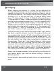
WARNING AND SAFETY NOTES Charging Before charging your batteries, it is critical that you determine the maximum allowable charge rate for your batteries. The X1 MF has the capability to charge at high rates that may not be suitable or safe for your particular batteries. For example, Lithium cells are typically safe to charge at 1C, or the total mAh/1000. A 1200mAh battery would have a 1C charge rate of 1.2 Amps. A 4200mAh battery would have a 1C charge rate of 4.2 Amps.
WARNING AND SAFETY NOTES Note: Lithium battery packs can be purchased with some cells in series and others in parallel. Parallel wired cells (indicated on the pack by the letter “P”) maintain a single cell’s voltage but increase capacity with each cell added. For example, 3 LiPo cells rated for 800mAh capacity each, wired in parallel would produce a pack rated for 3.7 Volts and 2400mAh.
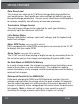
LITHIUM BATTERY CONNECTION DIAGRAM The X1 MF can be powered either from a wall outlet supplying 100-240VAC (50-60Hz) or from a 12VDC automotive battery. Make sure a 12VDC source battery is fully charged before using the X1 MF. A fully charged 12VDC automotive battery should read about 13.8V. NOTE: DC INPUT: The maximum charge circuit power is 80W. AC INPUT: The maximum charge circuit power is 50W.
LITHIUM BATTERY CONNECTION DIAGRAM Balancing Board: The balancing port lead polarity is critical! Verify that the black wire (negative) coming from the balancing board is connected to the negative port (-) on the charger. Failure to do so will damage the charger!! This image shows the correct way to connect your battery and the balancing board to the X1 MF before charging in the balance charge mode.
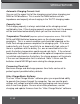
SELECT PROGRAM FLOW CHART 12 START PROGRAM SELECT LiPo BATT SELECT LiPo CHARGE 2.0A 7.4V (2S) SELECT LiPo FAST CHG 2.0A 7.4V (2S) SELECT LiPo STORAGE 2.0A 7.4V (2S) SELECT LiPo DISCHARGE 2.0A 7.4V (2S) Lilo BALANCE 2.0A 7.2V (2S) SELECT Lilo CHARGE 2.0A 7.2V (2S) SELECT Lilo FAST CHG 2.0A 7.2V (2S) SELECT Lilo STORAGE 2.0A 7.2V (2S) SELECT Lilo DISCHARGE 2.0A 7.2V (2S) LiFe BALANCE 2.0A 6.6V (2S) SELECT LiFe CHARGE 2.0A 6.6V (2S) SELECT LiFe FAST CHG 2.0A 6.
OPERATION Control and adjustment of the X1 MF is accomplished using the red rotary push button dial and the black Mode/Stop button. Mode/Stop Button Enter/Start Rotary Dial Enter/Start Rotary Dial This dial has many functions. Rotating the dial in both directions will scroll through menus and adjust parameters quickly and easily, and pressing down on the dial to commit parameters, begin processes, or store parameters on-screen.
LITHIUM BATTERY (LiPo/LiFe/LiIon) PROGRAM The X1 MF Lithium programs are only suitable for charging and discharging Lithium batteries with a nominal voltage of 3.7V, 3.6V and 3.3V per cell. Lithium charge termination methodology is referred to as CC/CV (Constant Current, Constant Voltage). Lithium charging begins by delivering a constant current to the battery as specified in the setup parameters.
LITHIUM BATTERY (LiPo/LiFe/LiIon) PROGRAM Press Dial Number Charging of cells current Charging time Battery voltage Charged capacity This screen displays the number of cells detected by the charger (R), and the number of cells you selected in the previous screen (S). If these numbers mismatch, go back to the previous screen and verify your settings. If your settings are correct, there may be a problem with one or more cells in your pack.
LITHIUM BATTERY (LiPo/LiFe/LiIon) PROGRAM previous screen and verify your settings. If your settings are correct, there may be a problem with one or more cells in your pack. Verify the pack total voltage (from the main leads) is within normal expected range. Press Dial Number Charging of cells current Battery voltage Charging time Charged capacity This screen displays the real-time status of the charge process.
LITHIUM BATTERY (LiPo/LiFe/LiIon) PROGRAM Press Dial Number Charging Battery of cells current voltage Charging time Supplied capacity settings are correct, there may be a problem with one or more cells in your pack. Verify the pack total voltage (from the main leads) is within normal expected range. This screen displays the real-time status of the charge process. Pressing the Mode/Stop button once will end the charge process and return you to the setup screen.
LITHIUM BATTERY (LiPo/LiFe/LiIon) PROGRAM Charge or Number Discharge of cells current with one or more cells in your pack. Verify the pack total voltage (from the main leads) is within normal expected range. Press Dial Battery voltage This screen displays the real-time status of the storage process. Pressing the Mode/Stop button once will end the storage process and return you to the setup screen.
NiMH/NiCD BATTERY PROGRAM These programs are for charging or discharging Nickel-Metal Hydride (NiMH) or Nickel-Cadmium (NiCd) batteries. CHARGING OF NIMH/NICD BATTERIES The standard charge mode for NiMH and NiCd batteries will use the charge current set by the user. NiMH CHARGE CURRENT 2.0A - + Battery type SELECT Pressing the dial once will allow you to set the charging amperage for the charge process. Refer to manufacturer specifications for maximum charge rates for your Nickel-based battery packs.
NiMH/NiCD BATTERY PROGRAM NiMH 2.0A AUT 000:13 9.52V 00320 Battery Elapsed Battery time Chargevoltage Charged type capacity current This screen displays the real-time status of the charging process. Pressing the Mode/Stop button once will end the charging process and return you to the setup screen. CHARGING NIMH/NICD BATTERIES IN RE-PEAK CHARGE MODE Applicable to NiMH and NiCd batteries only, in re-peak mode the charger can peak charge the battery once, twice, or three times in a row automatically.
NiMH/NiCD BATTERY PROGRAM Battery type Discharge current Battery voltage NiMH 0.1A 7.42V DSC 022:45 00919 Elapsed time This screen displays the real-time status of the discharge process. Pressing the Mode/Stop button once will end the discharge process and return you to the setup screen.
PB (LEAD-ACID) BATTERY PROGRAM Pb or Small Lead-Acid (SLA) batteries typically found in ATVs, lawn mowers and motorcycles require their own specific charging procedures. Pb batteries, as a rule, are unable to charge at higher rates like Nickel or Lithium-based batteries. Pb batteries should always be stored fully charged to avoid sulfation and cell degradation. Always consult the manufacturer’s recommendation for proper charging and charge rates of your Pb battery. Charge in a well ventilated area.
PB (LEAD-ACID) BATTERY PROGRAM Battery type Discharge current E lapsed time Battery voltage Discharged capacity This screen displays the real-time status of the discharge process. Pressing the Mode/Stop button once will end the discharge process and return you to the setup screen. USING THE HITEC CHARGE MASTER SOFTWARE The free “Hitec Charge Master” software gives you unparalleled ability to operate the charger through the computer.
BATTERY MEMORY SET The charger can store up to 10 different charge/discharge profiles for your convenience, and the stored profiles can be recalled quickly without having to go through the setup process.
BATTERY MEMORY SET TVC=YOUR RISK! 4.20V SELECT SELECT TEMPERATURE CUT-OFF 50C SELECT SELECT SAVE PROGRAM ENTER Set the process termination voltage. Range: 4.18V 4.30V. CAUTION: be sure to set/verify the correct end voltage of the type of cell you are charging. Over charging batteries can result in fire or explosion! If you are using the optional external Temperature Sensor, set the temperature cutoff. If you are not using the Temperature Sensor, leave this setting as-is.
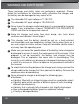
LITHIUM BATTERY METER You can check your battery’s total voltage and each cell’s individual voltage, as well as the highest and lowest cell voltages, when using the battery Balancing Board. Connect your Lithium battery as shown in the image below: 4.18 4.19 4.18V 4.19 4.17 4.17V This diagram shows the correct way to connect your battery to check individual cell votages. PROGRAM SELECT Li BATT METER Press Dial 4.13 4.12 4.13V 0.00 0.00 0.
MOTOR RPM TESTER The X1 MF can test brushless motor RPM if you have a motor equipped with a sensor port. To check motor RPM, please connect as follows: 1. Connect the motor to the ESC, turn off ESC and connect main battery. 2. Connect power to the X1 MF. 3. Insert the ESC radio lead into the SERVO/ESC port on the X1 MF. 4. Connect the sensor wire between the X1 MF and the motor. 5. Enter the Motor RPM Tester Program and set the initial pulse width to around 1480.
SERVO TESTER The X1 MF can test most digital and analog servos. To test for basic servo functionality, please connect as follows: 1. Connect a lithium battery to the balancing board. 2. Connect your servo to the SERVO/ESC port on the X1 MF. Pay close attention to the polarity: negative is farthest from the notch/key tab. 3. Turn the dial left and right to move the servo. Negative (black wire) This diagram shows the correct way to connect a servo to the X1 MF.
SYSTEM SETUP Upon first intitalization, the X1 MF default values are loaded. You can adjust these parameters by pressing the Mode/Stop button and scrolling to the System Set screen. Scroll through the various settings by turning the dial left or right. Pressing the dial once will enter the adjustment parameters for the selected setup variable. Once you make adjustments, press the dial again to return to the System Set menu. When you have completed changes, pressing Mode/Stop again will exit programming.
SYSTEM SETUP with enough time to charge 140% of the battery’s rated capacity. Delta Peak termination should, under normal circumstances, end the charge process within this allotted time. For example: Capacity Current Safety T ime 2000mAh 3300mAh 2.0A 3.0A (2000/2.0=1000)/11.9=84 minutes 1000mAh 1.2A (1000/1.2=833)/11.9=70 minutes Capacity Cut-Off ON 5000mAH SELECT SELECT SELECT Key Beep Buzzer ON ON SELECT SELECT Input Power Low Cut-Off 11.0V SELECT Ext. Temp Int.
VARIOUS INFORMATION DURING PROCESSES LOAD FACTORY SET ENTER SELECT VERSION 1.00 Press the dial for 5 seconds to restore the X1 MF to the firmware defaults. The last value on the system setup menu displays the current firmware version of the X1 MF. You can use a USB cable to update the X1 MF to the latest firmware version. Visit www.hitecrcd.com for more information.
WARNING AND ERROR MESSAGES The X1 MF has advanced error sensing logic to help protect the charger and your batteries in the event of a problem. The error messages below will display along with an audible alert. REVERSE POLARITY CONNECTION BREAK CONNECT ERROR CHECK MAIN PORT BALANCE CONNECT ERROR DC IN TOO LOW DC IN TOO HIGH CELL ERROR LOW VOLTAGE CELL ERROR HIGH VOLTAGE CELL ERROR VOLTAGE INVALID CELL NUMBER INCORRECT INT.TEMP.TOO HIGH EXT.TEMP.
SPECIFICATIONS SPECIFICATIONS AC Input 100-240V 60Hz DC Input 11-18V Charge circuit power AC Input 50W DC Input 80W Charge current range Discharge current power 0.1-10.0A Discharge current range 0.1-5.0A Current drain for balancing port 200mA/cell NiCd/NiMH battery cell count 1-15 Cells LiPo/LiFe/Lilon cell count 1-6 Cells Pb battery voltage 2-20V Net weight 525g (18.5oz) Dimension 135 x 112 x 60.9mm(5.34 x 4.4 x 2.4in.
RECOMMENDED ACCESSORIES Hitec External Temperature Sensor PN: 44159 Hitec Universal Balance Board PN: 44178 LIABILITY EXCLUSION This charger is designed and approved exclusively for use with the types of batteries stated in this Instruction Manual. Hitec RCD, USA accepts no liability of any kind if the charger is used for any purpose other than that stated.
CONFORMITY DECLARATION The Hitec RCD USA X1 MF charger satisfies all relevant and mandatory FCC and EC regulatory directives including the following: This symbol indicates that when this type of electronic device reaches the end of its service life, it cannot be disposed of with normal household waste and must be recycled. To find a recycling center near you, refer to the internet or your local phone directory for electronic waste recycling centers.
WARRANTY AND SERVICE ONE YEAR LIMITED WARRANTY For a period of one year from the date of purchase HITEC RCD USA, INC. shall REPAIR OR REPLACE, at our option, defective equipment covered by this warranty, otherwise the purchaser and/or consumer is responsible for any charges for the repair or replacement of the charger.
Distributed by Hitec RCD USA, Inc. www.hitecrcd.