
User's Manual


Setup Complete
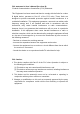
LED Display
Congratulations! You have successfully set up your router. If you have
any problems, see the sections below for help identifying the problem.
* Up to ten minutes on first connection, two minutes thereafter.
POWER: this LED turns on when power is connected and the
router is turned on. If it does not, your router is not receiving
power.
UPSTREAM/DOWNSTREAM: these LEDs blink while the router is
searching for a connection over the Internet, and shine steadily once
a connection is established. If they continue to blink for longer than
expected*, the router cannot make a connection.
LINE 1/LINE 2: (CVE Series only) these LEDs turn on if you have phone/
fax services.If you ordered one phone line LINE 1 turns on, and if you
ordered two lines, both LEDs turn on.
IP addresses
If your router is successfully connected to the network (see LED display)
but you cannot access the Internet from a connected computer, your
computer’s IP Address may be set up wrongly. In your computer’s control
panel either ensure that the computer is configured to receive an IP address
automatically (recommended) or ensure that it has a static IP address in the
range 192.168.0.2~192.168.0.254. For more information, consult your
Operating System’s document.
Configration interface
Your router has a configuration interface
allowing complete control over the
device’s behavior. In a Web browser, enter
192.168.0.1 in the address bar. In the screen
that displays, enter admin as the username
and password as the password.
Connection options
POWER
CABLECOMPUTERS
PHONES/
FAXES
WIRELESS
DEVICES
STEP
Safety Warnings
WARNING
DISCLAIMER
COPYRIGHT © 2011 HITRON TECHNOLOGIES, INC.
Notes
Wall-mounting lnstallation
The mounting holes seperated by 157mm/ 6.18inch on the
bottom of device. You may drive two nails or screws with the
head size in a diameter of 7.00mm/ 0.28inch and a thickness
of 2.7mm/ 0.11inch into the wall to make sure of the nails or
screws are capable of withstanding 2.5k load.You also can
use the little pack with tapping screws and plastic anchors in
box to mount this device on the wall. The steps of wall-mounted
installation are
(1) Drill two holes with diameters of 6.5mm/ 0.25inch, in distance
of 157mm/ 6.18inch on the wall.
(2) Nail the plastic anchors into the holes and make sure the
whole anchors were inserted in the wall.
(3) Screw the tapping screws in the anchors and expose the
appropriate length at the screw head to hang the device.
There are limitations if plastic anchors are used. The wall
surface must be:
1. Fir and pine with a thickness of over 32mm/ 1.25inch;timber
or plywood that is capable of withstanding 2.5k load.
2. Brick wall with a thickness of over 32mm/ 1.25inch.
3. Concrete wall with a thickness of over 32mm/ 1.25inch
4. Metal wall with a thickness of over 15mm/ 0.6inch
157mm (6.18inch)
103 mm (4
i
n
c
h)
Wall
Hole Drilling
Diameter 6.50mm/ 0.25inch
Tapping screw
Plasti
c anchor
Wall
The drilling orientation of the actual size is
included in the box.Before drilling holes
on the wall, you can place this orientation
diagram on the wall first and drill holes
P/N:0440010108N0(2A)
NCC Warning Statement
Article 12
Without permission, any company, firm or user shall not alter the frequency, increase the
power, or change the characteristics and functions of the original design of the certified
lower power frequency electric machinery.
Article 14
The application of low power frequency electric machineries shall not affect the naviga-
tion safety nor interfere a legal communication, if an interference is found, the service
will be suspended until improvement is made and the interference no longer exists.
The manufacturer assumes no liabilities with respect to the contents of this document.
The manufacturer also reserves the right to revise this document or update the content
thereof without any obligation to notify any person of such revisions or amendments.
Specifications subject to change without notice.
Risk of electrical shock. Do not expose the device to water or moisture. The device is a
high-performance communications device designed for home and office environments.
Do not use the device outdoors. Keep the device in an environment between 0°C ~ 40°C
(32°F ~104°F). To avoid overheating, do NOT place any object on top of the device. Do
not restrict the flow of air around the cable modem. The manufacturer assumes no
liabilities for damage caused by any improper use of the device.